

herunterladen

2004 Microchip Technology Inc. DS00889B-page 1
AN889
INTRODUCTION
An induction motor can run only at its rated speed when
it is connected directly to the main supply. However,
many applications need variable speed operations.
This is felt the most in applications where input power
is directly proportional to the cube of motor speed. In
applications like the induction motor-based centrifugal
pump, a speed reduction of 20% results in an energy
savings of approximately 50%.
Driving and controlling the induction motor efficiently
are prime concerns in today’s energy conscious world.
With the advancement in the semiconductor fabrication
technology, both the size and the price of semiconduc-
tors have gone down drastically. This means that the
motor user can replace an energy inefficient mechani-
cal motor drive and control system with a Variable
Frequency Drive (VFD). The VFD not only controls the
motor speed, but can improve the motor’s dynamic and
steady state characteristics as well. In addition, the
VFD can reduce the system’s average energy
consumption.
Although various induction motor control techniques
are in practice today, the most popular control tech-
nique is by generating variable frequency supply, which
has constant voltage to frequency ratio. This technique
is popularly known as VF control. Generally used for
open-loop systems, VF control caters to a large num-
ber of applications where the basic need is to vary the
motor speed and control the motor efficiently. It is also
simple to implement and cost effective.
The PIC16F7X7 series of microcontrollers have three
on-chip hardware PWM modules, making them
suitable for 3-phase motor control applications. This
application note explains how these microcontrollers
can be used for 3-phase AC induction motor control.
VF CONTROL
A discussion of induction motor control theory is
beyond the scope of this document. We will mention
here only the salient points of VF control.
The base speed of the induction motor is directly
proportional to the supply frequency and the number of
poles of the motor. Since the number of poles is fixed
by design, the best way to vary the speed of the
induction motor is by varying the supply frequency.
The torque developed by the induction motor is directly
proportional to the ratio of the applied voltage and the
frequency of supply. By varying the voltage and the fre-
quency, but keeping their ratio constant, the torque
developed can be kept constant throughout the speed
range. This is exactly what VF control tries to achieve.
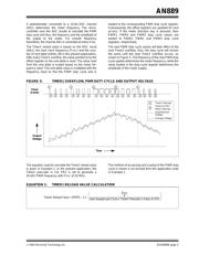
Figure 1 shows the typical torque-speed characteristics
of the induction motor, supplied directly from the main
supply. Figure 2 shows the torque-speed characteristics
of the induction motor with VF control.
Other than the variation in speed, the torque-speed
characteristics of the VF control reveal the following:
• The starting current requirement is lower.
• The stable operating region of the motor is
increased. Instead of simply running at its base
rated speed (N
B), the motor can be run typically
from 5% of the synchronous speed (N
S) up to the
base speed. The torque generated by the motor
can be kept constant throughout this region.
• At base speed, the voltage and frequency reach
the rated values. We can drive the motor beyond
the base speed by increasing the frequency
further. However, the applied voltage cannot be
increased beyond the rated voltage. Therefore,
only the frequency can be increased, which
results in the reduction of torque. Above the base
speed, the factors governing torque become
complex.
• The acceleration and deceleration of the motor
can be controlled by controlling the change of the
supply frequency to the motor with respect to
time.
Author: Rakesh Parekh
Microchip Technology Inc.
VF Control of 3-Phase Induction Motors
Using PIC16F7X7 Microcontrollers