
herunterladen
ã 2002 Microchip Technology Inc. DS00851B-page 1
AN851
INTRODUCTION
Among the many features built into Microchip’s
Enhanced FLASH Microcontroller devices is the capa-
bility of the program memory to self-program. This very
useful feature has been deliberately included to give
the user the ability to perform bootloading operations.
Devices like the PIC18F452 are designed with a desig-
nated “boot block”, a small section of protectable pro-
gram memory allocated specifically for bootload
firmware.
This application note demonstrates a very powerful
bootloader implementation for the PIC16F87XA and
PIC18F families of microcontrollers. The coding for the
two device families is slightly different; however, the
functionality is essentially the same. The goals of this
implementation stress a maximum performance and
functionality, while requiring a minimum of code space.
FIRMWARE
Basic Operation
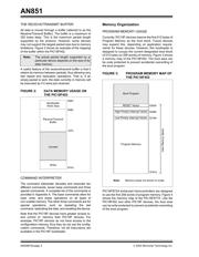
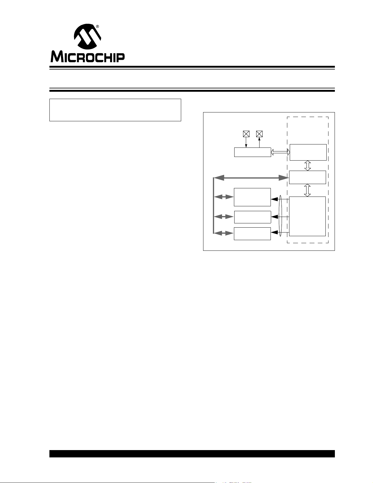
Figure 1 summarizes the essential firmware design of
the bootloader. Data is received through the USART
module, configured in Asynchronous mode for compat-
ibility with RS-232 and passed through the
transmit/receive engine. The engine filters and parses
the data, storing the information into a data buffer in
RAM. The command interpreter evaluates the com-
mand information within the buffer to determine what
should be done (i.e., Is the data written into a memory
unit? Is data read from a memory unit? Does the firm-
ware version need to be read?). Once the operation is
performed, data is passed back to the transmit/receive
engine to be transmitted back to the source, closing the
software flow control loop.
FIGURE 1: BOOTLOADER FUNCTIONAL
BLOCK DIAGRAM
COMMUNICATIONS
The microcontroller’s USART module is used to
receive and transmit data; it is configured as a UART to
be compatible with RS-232 communications. The
device can be set up in an application to bootload from
a computer through its standard serial interface. The
following communications settings are used:
• 8 data bits
•No parity
•1 STOP bit
The baud rate setting is variable depending on the
application. Baud rate selection is discussed later.
Author: Ross M. Fosler and
Rodger Richey
Microchip Technology Inc.
USART
Transmit/Receive
Engine
RAM
Buffer
Command
Interpreter
FLASH
Program
Memory
EE
Configuration
Data
Memory
TXRX
Registers
Bootloader
Control
Firmware
Data Bus
A FLASH Bootloader for PIC16 and PIC18 Devices