

herunterladen

A p p l i c At i o n n o t e
Page 1
Introduction
A standard optocoupler provides signal transfer between
an isolated input and output via an infrared Emitting Diode
(IRED) and a silicon phototransistor. Electrical isolation
is achieved by sending a beam of infrared energy to an
optical receiver in a single package with a light-conducting
medium between the emitter and detector. This mechanism
provides complete electrical isolation of electronic circuits
from input to output while transmitting information from
one side to the other, and from one voltage potential to
another.
This application note addresses the two common modes
of operation: Linear mode and digital logic mode.
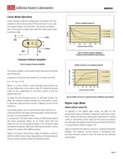
What is linear mode?
In linear mode, the optocoupler output produces a signal,
which is a copy of the input signal; its amplitude is a
product of the input signal and the Current Transfer Ratio
(CTR). In an optocoupler the CTR is specified as a ratio of
the collector current I
C
at the output to the forward cur-
rent, I
F
, applied to the Infrared Emitting Diode (IRED) on
the input side. A key condition for the Linear Mode is the
collector - emitter voltage, V
CE
is not in saturation.
What is digital logic mode?
In digital logic mode, the output signal is either logic high
(~Vcc) or low (ground level, for example), and ideally the
phototransistor on the receiver side goes into saturation
when the transistor output switches to logic high so that
the power consumption would be at the very low level.
Typically, for a silicon-based phototransistor, the satura-
tion voltage across the collector and emitter, V
CE
would
be at 0.3 V or less.
AN3010
Design Guideline for a Renesas/CEL Optocoupler
with Transistor Output
Authors: VanN.Tran CELStaApplicaonEngineer,OptoSemiconductors
LarrySiskenCELProductMarkengManager,OptoSemiconductors
WeiZ.Jiang,GraduateIntern(MSEE),SJSU
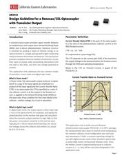
Parameter Definition
Current Transfer Ratio (CTR) is the gain of the optocoupler.
It is the ratio of the phototransistor collector current to the
IRED forward current.
CTR = (I
C
/ I
F
) * 100
It is expressed as a percentage (%).
The CTR depends on the current gain (hfe) of the transistor,
the supply voltage to the phototransistor, the forward current
through the IRED and operating temperature.
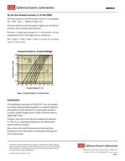
Below is the CTR vs. Forward Current, I
F
graph of the
PS2501A-1-A.
Forward Current IF (mA)
Current Transfer Ratio CTR (%)
Current Transfer Ratio vs. Forward Current
300
200
250
150
100
50
0
0.01 0.1
1 10 100
Sample A
B
C
VCE = 5V
n = 3
Fig 1: CTR vs. Forward Current, I
F
.
This application note is written around Renesas
phototransistor optocoupler PS2501A-1-A in DIP 4 package,
the measurements were done at nominal room temperature,
the common collector circuit configuration was used and
was operating at 5 Volts, a common operating voltage for
use with digital circuits, and in other situations where data
or pulse-edge events communicate between units. Since
the emitter current is approximately equal to collector
current, I
E
=~ I
C
, they will be used interchangeably in this
application note.