

herunterladen

For technical support and more information, see inside back cover or visit www.ti.com/powertrends
PT5100/6100/6210/6300 Series
Power Trends’ PT Series of Integrated Switching Regu-
lators (ISRs) provide several configuration options
for removing internally generated heat. To maximize the
heat transfer and space efficiency of the PT Series, they
can be mounted in vertical, horizontal, or surface mount
configurations.
Background/Heat Transfer Modes
The PT Series products utilize all three modes of heat
transfer; conduction, convection, and radiation. Conduction
dominates, conducting 60% of the heat to the leads and
outer package surfaces. Of the remaining 40%, approxi-
mately 30% is transferred by convection, and the rest by
radiation.
Conduction heat transfer occurs when the energy from
the heating surface starts a vibratory motion of the atoms and
molecules in material. When the heat reaches the package
boundaries, air begins to cool the unit. The constant that
governs the conduction process is called thermal conductiv-
ity. If the thermal conductivity is known, the thermal
resistance can be determined by taking into account the ge-
ometry of the package and the ambient temperature. Package
designs with low thermal conductivity and/or large spatial
dimensions tend to have high thermal resistances. Once
optimization of these two issues have been accomplished,
provisions must be made to efficiently remove the heat from
the package surface. During the design of the PT Series
products, extensive thermal computer simulations at various
operating conditions and extensive temperature chamber
testing were done to ensure reliable operation.
There are two types of convection heat transfer, natural
and forced. Natural convection occurs when the air density
changes due to the heating of the air. In natural convection,
the amount of heat driven off from a body is strictly a func-
tion of the surface temperature, surface area exposed to the
ambient air, and the ambient temperature. In many cases,
natural convection sets up an airflow of 0 to 40 LFM. An
airflow of 40 to 60 LFM is defined as “free air convection”.
When natural or free air convection is not enough to prop-
erly cool the part, forced air convection must be used.
Forced air convection uses moving air to remove heat
from the package. According to industry convention, forced
air convection is generally greater than 60 LFM. This mode
of heat transfer is a function of the air velocity only. These
velocities usually require the use of a fan. Usually, forced air
convection is needed only when the ambient temperature is
greater than 60 or 70°C for PT Series products.
Radiation, the least active of the three modes, is an elec-
tromagnetic heat transfer mechanism. It requires no medium
to transfer the heat, such as air or a solid. In the PT Series
design, radiation aids in heat transfer working in concert with
natural convection. If free air convection or forced convection
is used, radiation adds very little to the heat transfer process.
Table 5
DEFINITION OF TERMS
Term . . . . . . . . . . . . . . . . . . . . . Sym Units
Thermal resistance, junction to tab θ
JT
°C/W
Thermal resistance, junction to ambient θ
JA
°C/W
Thermal resistance, junction to sink θ
JS
°C/W
Thermal resistance, tab to sink . θ
TS
°C/W
Thermal resistance, sink to ambient θ
SA
°C/W
Power dissipated . . . . . . . . . . . . P
D
Watts
Power input . . . . . . . . . . . . . . . P
IN
Watts
Power output . . . . . . . . . . . . . . P
OUT
Watts
Efficiency . . . . . . . . . . . . . . . . . η %
Ambient temperature . . . . . . . . T
A
°C
Junction temperature, control IC T
J
°C
Heatsink temperature . . . . . . . . T
H
°C
Thermal Resistance
Thermal resistance restricts the amount of heat that can
transfer through a body. It is analogous to electrical resis-
tance. The result of this resistance is a temperature
difference, also analogous to the voltage difference in an elec-
trical circuit. The following general equation applies when
conduction heat transfer occurs:
(1) . . . . .
θ = t/kA
where: .t is the thickness of the body
. . . . . . .k is the thermal conductivity
. . . . . . .A is the area perpendicular to the heat flow
. . . . . . .
θ is the thermal resistance
Thermal resistances, from junction to ambient, for the
various PT Series products are shown on their respective data
sheets. In general,
θ
JA
is a function of the airflow, ambient
temperature, and geometry of the product. These values are
conservative and there will be slight differences when airflow
and ambient temperatures vary.
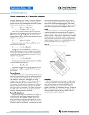
Thermal Model
Before thermal resistances can be used to find the operat-
ing temperatures of the PT Series products, the efficiency
Application Notes—AN7
Thermal Considerations for PT Series ISRs
SLTA007A
(Revised 6/30/2000)