


herunterladen
Reflowable Thermal Protection (RTP) Device for
Automotive HVAC and Cooling Fan Systems
APPLICATION NOTE
www.circuitprotection.com
PowerFET Failure in Harsh Environments
In the harsh automotive environment, power Field Effect
Transistors (powerFETs) are routinely subjected to extreme
temperature variations and thermo-mechanical stress.
Intermittent shorts, cold operating environments, high arcing
or noisy short circuits, as well as inductive loads and multiple
short circuits can, over time, fatigue the device and cause it
to fail in open, short or resistive mode.
Although powerFETs are increasingly robust, they are prone to
failures which can occur very quickly if their ratings are
exceeded. If the maximum operating voltage of a powerFET is
exceeded, it goes into avalanche breakdown. If the energy
contained in the transient overvoltage is above the rated
avalanche energy level, the device will fail; causing a destructive
thermal event that may result in smoking, flame or desoldering.
Automotive powerFETs have been shown to be more prone
to fatigue and failure than devices that are installed in less
demanding applications. When comparing powerFET failure
rates over time, devices used in harsh environments, such as
automotive applications, exhibit greater ppm failure rates.
After five years in the field the difference can be more than a
factor of ten.
Although a powerFET may pass initial testing, it has been
demonstrated that, given certain conditions, random weak
points in the device can result in field failure. Even in situations
where the powerFET is functioning within specified operating
conditions, random and unpredictable resistive shorts at varying
resistance values have been reported.
The resistive mode failure is of particular concern, not only for
the powerFET but for the Printed Circuit Board (PCB). As
little as 10W may generate a localized hot spot of more than
180°C, well above the typical PCB’s glass transition
temperature of 135°C, damaging the board’s epoxy structure
and leading to a thermal event.
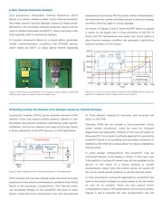
Figure 1 describes a scenario where a failed powerFET may not
generate a hard short overcurrent condition but rather a resistive
short, producing unsafe temperatures through I
2
R heating. In this
case the resulting current may not be high enough to blow a
standard fuse and stop thermal runaway on the PCB.
Figure 1. PowerFET failure in resistive mode can lead to unsafe
overtemperature conditions.
Verzeichnis
- ・ Blockdiagramm on Seite 2
- ・ Technische Daten on Seite 4