
herunterladen

Application Report
SCEA027A - September 2002
1
Application of the Texas Instruments
AUC Sub-1-V Little Logic Devices
Chris Maxwell and Tomdio Nana Standard Linear & Logic
ABSTRACT
Power consumption and speed are always concerns in electronic system logic design. Texas
Instruments (TI) announces the industry’s first sub-1-V logic family that provides significant
benefits to portable consumer electronics by operating at low power and high speed, while
maintaining overall system signal integrity. TI’s next-generation logic family is the advanced
ultra-low-voltage CMOS (AUC) family. Although optimized for 1.8-V operation, AUC logic
supports mixed-voltage systems because it is compatible with 0.8-V, 1.2-V, 1.5-V and 2.5-V
devices. The AUC logic inputs tolerate 3.6-V signals, thus enabling level-translation down
from 3.3-V nodes to lower-voltage nodes. Further, AUC logic has the I
off
feature, which
supports the partial-power-down mode of operation. This application report discusses AUC
Little Logic device features, characteristics, and applications.
Keywords: 0.8 V, 1.2 V, 1.5 V, 1.8 V, 2.5 V, 3.3-V tolerant, AUC, electrical performance, I
off
,
level translation, Little Logic, open drain, overvoltage protection, partial power down, signal
integrity, ULTTL
Contents
1 Introduction 4. . . . . . . . . . . . . . . . . . . . . . . . . . . . . . . . . . . . . . . . . . . . . . . . . . . . . . . . . . . . . . . . . . . . . . . . .
2 AUC Little Logic Features 4. . . . . . . . . . . . . . . . . . . . . . . . . . . . . . . . . . . . . . . . . . . . . . . . . . . . . . . . . . . .
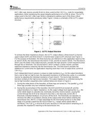
2.1 Novel Output Structure 4. . . . . . . . . . . . . . . . . . . . . . . . . . . . . . . . . . . . . . . . . . . . . . . . . . . . . . . . . . . .
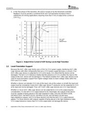
2.2 Level-Translation Support 6. . . . . . . . . . . . . . . . . . . . . . . . . . . . . . . . . . . . . . . . . . . . . . . . . . . . . . . . .
2.3 Power-Off Support 7. . . . . . . . . . . . . . . . . . . . . . . . . . . . . . . . . . . . . . . . . . . . . . . . . . . . . . . . . . . . . . . .
3 AUC Little Logic Device Characteristics 7. . . . . . . . . . . . . . . . . . . . . . . . . . . . . . . . . . . . . . . . . . . . . . .
3.1 Input Characteristics 7. . . . . . . . . . . . . . . . . . . . . . . . . . . . . . . . . . . . . . . . . . . . . . . . . . . . . . . . . . . . . .
3.1.1 Input Capacitance 7. . . . . . . . . . . . . . . . . . . . . . . . . . . . . . . . . . . . . . . . . . . . . . . . . . . . . . . . . .
3.1.2 Input Voltage Tolerance 7. . . . . . . . . . . . . . . . . . . . . . . . . . . . . . . . . . . . . . . . . . . . . . . . . . . . .
3.1.3 Slow-Input-Edge-Rate Compatibility 8. . . . . . . . . . . . . . . . . . . . . . . . . . . . . . . . . . . . . . . . . .
3.2 Electrical Characteristics 11. . . . . . . . . . . . . . . . . . . . . . . . . . . . . . . . . . . . . . . . . . . . . . . . . . . . . . . . .
3.2.1 AC Performance 11. . . . . . . . . . . . . . . . . . . . . . . . . . . . . . . . . . . . . . . . . . . . . . . . . . . . . . . . . .
3.2.2 DC Performance 13. . . . . . . . . . . . . . . . . . . . . . . . . . . . . . . . . . . . . . . . . . . . . . . . . . . . . . . . . .
3.3 Power Consumption 14. . . . . . . . . . . . . . . . . . . . . . . . . . . . . . . . . . . . . . . . . . . . . . . . . . . . . . . . . . . . .
4 Design Issues and AUC Little Logic Solutions 16. . . . . . . . . . . . . . . . . . . . . . . . . . . . . . . . . . . . . . . .
4.1 Signal Integrity 16. . . . . . . . . . . . . . . . . . . . . . . . . . . . . . . . . . . . . . . . . . . . . . . . . . . . . . . . . . . . . . . . . .
4.2 Mixed-Voltage-Mode Data Communication 19. . . . . . . . . . . . . . . . . . . . . . . . . . . . . . . . . . . . . . . . . .
4.3 Partial Power Down 20. . . . . . . . . . . . . . . . . . . . . . . . . . . . . . . . . . . . . . . . . . . . . . . . . . . . . . . . . . . . . .
4.4 Low Power Consumption 21. . . . . . . . . . . . . . . . . . . . . . . . . . . . . . . . . . . . . . . . . . . . . . . . . . . . . . . . .
TI and Widebus are trademarks of Texas Instruments.