
herunterladen

This is information on a product in full production.
July 2015 DocID15457 Rev 12 1/165
SPC56EL60x, SPC56EL54x,
SPC564L60x, SPC564L54x
32-bit Power Architecture® microcontroller for automotive
SIL3/ASILD chassis and safety applications
Datasheet - production data
Features
High-performance e200z4d dual core
32-bit Power Architecture® technology CPU
Core frequency as high as 120 MHz
Dual issue five-stage pipeline core
Variable Length Encoding (VLE)
Memory Management Unit (MMU)
4 KB instruction cache with error detection
code
Signal processing engine (SPE)
Memory available
– 1 MB flash memory with ECC
– 128 KB on-chip SRAM with ECC
– Built-in RWW capabilities for EEPROM
emulation
SIL3/ASILD innovative safety concept:
LockStep mode and Fail-safe protection
– Sphere of replication (SoR) for key
components (such as CPU core, eDMA,
crossbar switch)
– Fault collection and control unit (FCCU)
– Redundancy control and checker unit
(RCCU) on outputs of the SoR connected
to FCCU
– Boot-time Built-In Self-Test for Memory
(MBIST) and Logic (LBIST) triggered by
hardware
– Boot-time Built-In Self-Test for ADC and
flash memory triggered by software
– Replicated junction temperature sensor
– Non-maskable interrupt (NMI)
– 16-region memory protection unit (MPU)
– Clock monitoring units (CMU)
– Power management unit (PMU)
– Cyclic redundancy check (CRC) unit
Decoupled Parallel mode for high-performance
use of replicated cores
Nexus Class 3+ interface
Interrupts
– Replicated 16-priority controller
– Replicated 16-channel eDMA controller
GPIOs individually programmable as input,
output or special function
Three 6-channel general-purpose eTimer units
2 FlexPWM units
– Four 16-bit channels per module
Communications interfaces
– 2 LINFlexD channels
– 3 DSPI channels with automatic chip select
generation
– 2 FlexCAN interfaces (2.0B Active) with 32
message objects
– FlexRay module (V2.1 Rev. A) with 2
channels, 64 message buffers and data
rates up to 10 Mbit/s
Two 12-bit analog-to-digital converters (ADCs)
– 16 input channels
– Programmable cross triggering unit (CTU)
to synchronize ADCs conversion with timer
and PWM
Sine wave generator (D/A with low pass filter)
On-chip CAN/UART bootstrap loader
Single 3.0 V to 3.6 V voltage supply
Ambient temperature range –40 °C to 125 °C
Junction temperature range –40 °C to 150 °C
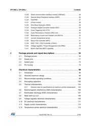
LFBGA257 (14 x 14 mm)
LQFP100 (14 x 14x 1.4 mm)
LQFP144 (20 x 20 x 1.4 mm)
www.st.com
Verzeichnis
- ・ Konfiguration des Pinbelegungsdiagramms on Seite 23
- ・ Abmessungen des Paketumrisses on Seite 34 Seite 35 Seite 36 Seite 37 Seite 38
- ・ Teilenummerierungssystem on Seite 153
- ・ Blockdiagramm on Seite 10
- ・ Technische Daten on Seite 98 Seite 99 Seite 127
- ・ Anwendungsbereich on Seite 105
- ・ Elektrische Spezifikation on Seite 98 Seite 99 Seite 100 Seite 101 Seite 102