


herunterladen

TBD
MAPBGA–225
15 mm x 15 mm
QFN12
##_mm_x_##mm
SOT-343R
##_mm_x_##mm
PKG-TBD
## mm x ## mm
257 MAPBGA
(14 x 14 mm)
473 MAPBGA
(19 x 19 mm)
Freescale Semiconductor
Data Sheet: Technical Data
Document Number: MPC5675K
Rev. 7, 5/2012
MPC5675K
© Freescale Semiconductor, Inc., 2009–2012. All rights reserved.
1 Introduction
1.1 Document overview
This document provides electrical specifications, pin
assignments, and package diagrams for the Qorivva
MPC5675K series of microcontroller units (MCUs).
1.2 Description
The Qorivva MPC5675K microcontroller, a SafeAssure
solution, is a 32-bit embedded controller designed for
advanced driver assistance systems with RADAR, CMOS
imaging, LIDAR and ultrasonic sensors, and multiple 3-phase
motor control applications as in hybrid electric vehicles
(HEV) in automotive and high temperature industrial
applications.
A member of Freescale Semiconductor’s Qorivva
MPC5500/5600 family, it contains the Book E compliant
Power Architecture technology core with Variable Length
Encoding (VLE). This core complies with the Power
Architecture embedded category, and is 100 percent user
mode compatible with the original Power PC user
instruction set architecture (UISA). It offers system
performance up to four times that of its MPC5561
predecessor, while bringing you the reliability and familiarity
of the proven Power Architecture technology.
A comprehensive suite of hardware and software
development tools is available to help simplify and speed
system design. Development support is available from
leading tools vendors providing compilers, debuggers and
simulation development environments.
Qorivva MPC5675K
Microcontroller Data Sheet
1 Introduction. . . . . . . . . . . . . . . . . . . . . . . . . . . . . . . . . . . . . . . . 1
1.1 Document overview . . . . . . . . . . . . . . . . . . . . . . . . . . . . 1
1.2 Description . . . . . . . . . . . . . . . . . . . . . . . . . . . . . . . . . . . 1
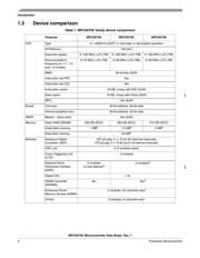
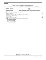
1.3 Device comparison . . . . . . . . . . . . . . . . . . . . . . . . . . . . . 2
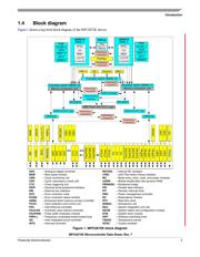
1.4 Block diagram . . . . . . . . . . . . . . . . . . . . . . . . . . . . . . . . . 5
1.5 Feature list . . . . . . . . . . . . . . . . . . . . . . . . . . . . . . . . . . . 6
1.6 Feature details . . . . . . . . . . . . . . . . . . . . . . . . . . . . . . . . 7
2 Package pinouts and signal descriptions . . . . . . . . . . . . . . . .17
2.1 Package pinouts . . . . . . . . . . . . . . . . . . . . . . . . . . . . . .17
2.2 Pin descriptions . . . . . . . . . . . . . . . . . . . . . . . . . . . . . .20
3 Electrical characteristics. . . . . . . . . . . . . . . . . . . . . . . . . . . . . 69
3.1 Introduction . . . . . . . . . . . . . . . . . . . . . . . . . . . . . . . . . .69
3.2 Absolute maximum ratings . . . . . . . . . . . . . . . . . . . . . .69
3.3 Recommended operating conditions . . . . . . . . . . . . . . 70
3.4 Thermal characteristics . . . . . . . . . . . . . . . . . . . . . . . . 72
3.5 Electromagnetic interference (EMI) characteristics . . . 73
3.6 Electrostatic discharge (ESD) characteristics. . . . . . . . 74
3.7 Static latch-up (LU) . . . . . . . . . . . . . . . . . . . . . . . . . . . .74
3.8 Power Management Controller (PMC) electrical
characteristics. . . . . . . . . . . . . . . . . . . . . . . . . . . . . . . . 74
3.9 Supply current characteristics. . . . . . . . . . . . . . . . . . . . 76
3.10 Temperature sensor electrical characteristics. . . . . . . . 77
3.11 Main oscillator electrical characteristics . . . . . . . . . . . .77
3.12 FMPLL electrical characteristics . . . . . . . . . . . . . . . . . . 78
3.13 16 MHz RC oscillator electrical characteristics. . . . . . . 79
3.14 ADC electrical characteristics . . . . . . . . . . . . . . . . . . . .79
3.15 Flash memory electrical characteristics . . . . . . . . . . . . 84
3.16 SRAM memory electrical characteristics . . . . . . . . . . .86
3.17 GP pads specifications . . . . . . . . . . . . . . . . . . . . . . . . . 87
3.18 PDI pads specifications . . . . . . . . . . . . . . . . . . . . . . . .88
3.19 DRAM pad specifications . . . . . . . . . . . . . . . . . . . . . . . 90
3.20 RESET
characteristics . . . . . . . . . . . . . . . . . . . . . . . . . 96
3.21 Reset sequence . . . . . . . . . . . . . . . . . . . . . . . . . . . . . . 96
3.22 Peripheral timing characteristics . . . . . . . . . . . . . . . . .102
4 Package characteristics . . . . . . . . . . . . . . . . . . . . . . . . . . . . 126
4.1 Package mechanical data. . . . . . . . . . . . . . . . . . . . . . 126
5 Orderable parts . . . . . . . . . . . . . . . . . . . . . . . . . . . . . . . . . . 132
6 Reference documents . . . . . . . . . . . . . . . . . . . . . . . . . . . . . 132
7 Document revision history . . . . . . . . . . . . . . . . . . . . . . . . . .132
Verzeichnis
- ・ Konfiguration des Pinbelegungsdiagramms on Seite 15 Seite 20 Seite 87 Seite 88 Seite 90
- ・ Abmessungen des Paketumrisses on Seite 17 Seite 18 Seite 19 Seite 20 Seite 21
- ・ Blockdiagramm on Seite 5
- ・ Technische Daten on Seite 69 Seite 70
- ・ Elektrische Spezifikation on Seite 69 Seite 70 Seite 71 Seite 72 Seite 73