
herunterladen
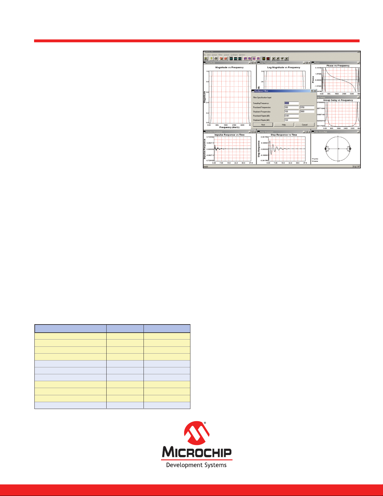
Comparison - Filter Design vs. Filter Design Lite
M icrochip Technology Incorporated
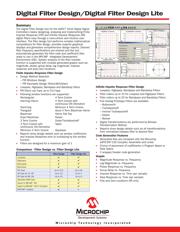
Summary
The Digital Filter Design tool for the dsPIC
®16-bit Digital Signal
Controllers
makes designing, analyzing and implementing Finite
Impulse Response (FIR) and Infinite Impulse Response (IIR)
digital filters easy through a menu-driven and intuitive user
interface. The filter design tool performs complex mathematical
computations for filter design, provides superior graphical
displays and generates comprehensive design reports. Desired
filter frequency specifications are entered and the tool
automatically generates the filter code and coefficient files
ready to use in the MPLAB
®
Integrated Development
Environment (IDE). System analysis of the filter transfer
function is supported with multiple generated graphs such as:
magnitude, phase, group delay, log magnitude, impulse
response and pole/zero locations.
Finite Impulse Response Filter Design
· Design Method Selection
– FIR Windows Design
– FIR Equiripple Design (Parks-McClellan)
· Lowpass, Highpass, Bandpass and Bandstop filters
· FIR filters can have up to 513 taps
· Following window functions are supported:
Rectangular 4 Term Cosine
Hanning (Hann) 4 Term Cosine with
continuous 5th Derivative
Hamming Minimum 4 Term Cosine
Triangular Good 4 Term Blackman Harris
Blackman Harris Flat To p
Exact Blackman Kaiser
3 Term Cosine Dolph-Tschebyscheff
3 Term Cosine with Taylor
continuous 3rd Derivative
Minimum 3 Term Cosine Gaussian
· Reports show design details such as window coefficients
and Impulse Response prior to multiplying by the window
function
· Filters are designed for a maximum gain of 1
Digital Filter Design/Digital Filter Design Lite
Infinite Impulse Response Filter Design
· Lowpass, Highpass, Bandpass and Bandstop Filters
· Filter orders up to 10 for Lowpass and Highpass Filters
· Filter orders up to 20 for Bandpass and Bandstop Filters
· Five Analog Prototype Filters are available:
– Butterworth
– Tschebyscheff
– Inverse Tschebyscheff
– Elliptic
– Bessel
· Digital Transformations are performed by Bilinear
Transformation Method
· Reports show design details such as all transformations
from normalized lowpass filter to desired filter
Code Generation Features
· Generated files are compliant with the Microchip
dsPIC30F C30 Compiler, Assembler and Linker
· Choice of placement of coefficients in Program Space or
Data Space
· C wrapper/header code generation
Graphs
· Magnitude Response vs. Frequency
· Log Magnitude vs. Frequency
· Phase Response vs. Frequency
· Group Delay vs. Frequency
· Impulse Response vs. Time (per sample)
· Step Response vs. Time (per sample)
· Pole and Zero Locations (IIR only)
High-pass
Up to 513 Up to 64FIR Taps
Band-pass
Band-stop
Up to 10 Up to 4IIR Taps for LP, HP
Up to 20 Up to 8IIR Taps for BP, BS
Generate ASM Code
Export to MPLAB® IDE
Export to MPLAB® C30 C Compiler
MATLAB® Support
✔
✔
✔
✔
✔
✔
✔
✔
✔
✔
✔
✔
✔✔
✔
Low-pass
Filter Design Filter Design Lite
—
Verzeichnis