
herunterladen

© 2009 Microchip Technology Inc. DS01256A-page 1
AN1256
INTRODUCTION
The simulation models for Microchip’s power MOSFET
drivers aid in the design and analysis of various circuits
by allowing for detailed simulation of the circuit being
designed.
This application note covers the function and use of the
SPICE simulation models, tips on solving convergence
issues, and provides a boost converter example using
the TC1410N simulation model.
MODEL DESCRIPTION
The power MOSFET driver models were written and
tested in Orcad’s PSPICE 10.0 which is equivalent to
Cadence PSPICE 15.x. The type of modeling
technique that was used to model the MOSFET drivers
is called “Macro Modeling”. The model is based on
treating the MOSFET driver as a black box and using
mathematical equivalents of the internal functions.
There are many advantages of macro modeling over
transistor level modeling. Since the internal circuitry
has been simplified to mathematically represent the
functions, the simulation runs much faster and is more
robust. This allows the user to simulate their circuitry at
the board or system level with the MOSFET drivers
within a reasonable simulation time.
However with transistor level modeling, there are many
interactions between the transistors. For example how
voltage and current vary with time or temperature. In a
macro model, some of these variations have to be
simplified. For example, the quiescent current will vary
smoothly over temperature for an actual IC or transistor
level model. To model this using the macro modeling
technique, a look-up table is used. This causes the
macro model results to not be as smooth as the actual
IC. However the discrepancies between the look-up
table and the actual IC performance are minimal.
Parameters Covers By Model
The power MOSFET driver simulation model covers a
wide aspect of the MOSFET driver’s electrical specifi-
cations. Not only does the model cover voltage,
current, and resistance of the MOSFET driver, but they
also cover the temperature effects on the behavior of
the MOSFET driver.
The models have been verified by comparing simula-
tion results against actual driver behavior and
specifications contained in the appropriate MOSFET
driver data sheet.
The MOSFET driver simulation models have not been
verified outside of the specification range listed in the
MOSFET driver data sheet. The behavior under these
conditions can not be guaranteed that it will match the
actual driver performance.
Using The Power MOSFET Simulation
Models
The MOSFET driver simulation models are provided in
netlist format. This is useful for simulating the models
in a number of different simulators. Please refer to your
simulator software reference manual on how to create
a schematic symbol and relating a netlist to the symbol.
All SPICE simulation schematic tools are different in
their creation of a schematic symbol and relating it to
the library file.
The MOSFET driver model is in sub circuit format. An
example of this sub circuit can be found in Figure 1.
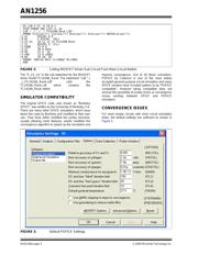
FIGURE 1: TC1410N Sub Circuit.
This model has four nodes: Input, Output, Positive
Supply, and Negative Supply that correspond to the
appropriate pins of the TC1410N MOSFET driver.
Certain MOSFET driver netlist models have more
nodes that correlate to the addition features present on
those MOSFET drivers. However their sub circuit for-
mat follows the same node naming convention as
shown in Figure 1.
The MOSFET driver models are self contained and
require no other models or libraries to run. Figure 2
shows how to call the MOSFET driver sub circuit from
a netlist.
Author: Cliff Ellison (Microchip Technology Inc.)
Ron Wunderlich (Innovative Ideas and
Design)
.SUBCKT TC1410N 1234
* ||||
* |||Negative Supply
* | | Positive Supply
*|Output
* Input
.
... (Continuation of TC1410N Netlist)
.
.ENDS TC1410N_RevA
Microchip’s Power MOSFET Driver Simulation Models