
herunterladen
2003 Microchip Technology Inc. DS00770B-page 1
M
AN770
INTRODUCTION
Pulse Width Modulation (PWM) fan speed control
methodology pulse-width modulates a fan’s full-rated
power supply voltage at a low frequency, typically
30 Hz. A typical PWM circuit, consisting of a transistor
in series with a fan, can be small and inexpensive
because it is either fully on or completely off. This effi-
cient control methodology affords a very wide speed-
control range (typically 10% to 100% of full speed)
because the fan motor is exposed to its full-rated
voltage during the active portion of the PWM cycle.
PWM control works with standard, two-wire Brushless
DC (BDC) fans of various sizes. However, very large
fans (with operating currents of 0.5A or more) can
sometimes produce an unwanted acoustic noise com-
ponent when operated with PWM control. In most
cases, this is remedied by slowing the edges of the out-
put switching transistor with the addition of a small
capacitor. In the most severe cases, this may not be
sufficient, which forces the user to consider linear
voltage speed control.
Linear voltage speed control operates by continuously
varying the DC supply across the fan. The lower the
voltage, the slower the fan operates. While this meth-
odology eliminates the acoustic noise issue described
earlier, it creates other problems. For example, the out-
put device must be operated as a linear amplifier
(instead of a switch), so its size and cost must be
increased and may require heatsink mounting. Also,
most fans cannot be operated at less than half the full-
rated supply voltage, thereby limiting the fan speed
control range to only 50% to 100% of maximum. With
the inherent limitations of linear voltage speed control
in mind, this application note describes a low-cost tech-
nique for operating the TC642/646/648 PWM Fan
Managers in linear voltage speed control mode.
M
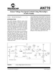
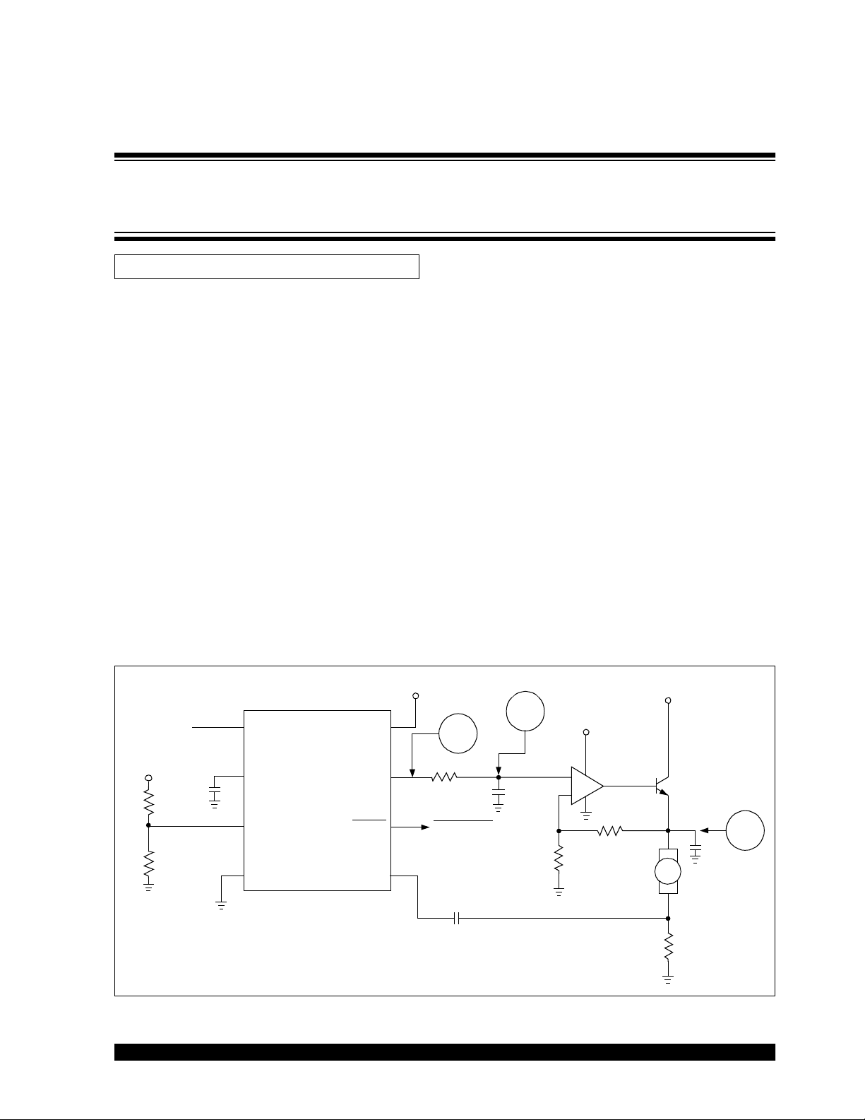
FIGURE 1: Linear Voltage Speed Control Circuit.
Author: Microchip Technology Inc.
TC646
1
2
3
4
8
7
6
5
V
IN
V
IN
(1.5V to 2.6V)
C
F
V
AS
GND
V
DD
V
OUT
FAULT
SENSE
R
1
R
2
+5V
+5V
C
1
0.47 µF
C
2
10 µF
C
3
0.1 µF
U1
R
3
120 kΩ
R
5
1.3 kΩ
R
4
1kΩ
R
6
0.5Ω
FAN FA ULT
*Trace
#1
+
+
-
+12V
+12V
Q
1
TIP31A
U
2
LM358
(1A)
*See Figures 2 and 3.
*Trace
#2
*Trace
#3
Fan
C
4
1µF
-
+
Linear Voltage Fan Speed Control Using Microchip's
TC64X Family