

herunterladen
Application Report
SLVA464E–May 2011–Revised September 2013
Creating a Universal Car Charger for USB Devices From
the TPS54240 and TPS2511
Robert Taylor and Steve Schnier................................................... Industrial DC/DC SWIFT(TM) Converters
ABSTRACT
This application report describes how to design a Universal Car Charger for USB devices. The TPS2511
auto-detect feature monitors USB data line voltage, and automatically provides the correct electrical
signatures on the data lines to charge complaint devices among the following dedicated charging
schemes:
1. Divider DCP for Apple
®
devices, required to apply 2.7 V/2.0 V or 2.0 V/2.7 V on the D+/D– lines
respectively
2. BC1.2 DCP, required to short the D+ line to the D– line
3. 1.2 V/1.2 V on the D+/D– lines for Samsung Tablets
The form factor of the design complies to the UL standard 2089 and ANSI/SAE J563 specification and can
be easily adapted to meet other form factors.
Contents
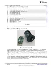
1 Universal Car Charger Design Requirements ........................................................................... 2
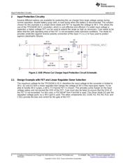
2 Input Protection Circuitry ................................................................................................... 4
2.1 Design Example with FET and Linear Regulator Zener Selection .......................................... 4
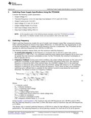
3 Switching Power Supply Specifications Using the TPS54240 ........................................................ 5
3.1 Switching Frequency .............................................................................................. 5
3.2 Output Inductor Selection ......................................................................................... 6
3.3 Output Capacitor ................................................................................................... 6
3.4 Catch Diode ......................................................................................................... 7
3.5 Input Capacitor ..................................................................................................... 8
3.6 Slow Start Capacitor ............................................................................................... 8
3.7 Bootstrap Capacitor Selection .................................................................................... 8
3.8 Undervoltage Lockout Set Point ................................................................................. 8
3.9 Output Voltage and Feedback Resistors Selection ........................................................... 9
3.10 Compensation ...................................................................................................... 9
4 Current-Limit Switch Specifications Using the TPS2511 ............................................................. 11
4.1 Selecting the Current-Limit Resistor ........................................................................... 11
4.2 DCP Auto-Detect ................................................................................................. 11
5 Experimental Results ..................................................................................................... 13
6 Board Layout ............................................................................................................... 18
List of Figures
1 Universal Car Charger...................................................................................................... 2
2 USB iPhone Car Charger Input Protection Circuit Schematic ........................................................ 4
3 5-V Output TPS54240 Design Example ................................................................................. 6
4 5-V Output TPS2511 Design Example ................................................................................. 11
5 TPS2511 DCP Auto-Detect Functional Diagram...................................................................... 12
6 Efficiency Versus Load Current Prior to the Load Switch............................................................ 13
SWIFT is a trademark of Texas Instruments.
Apple, iPod, iPhone are registered trademarks of Apple Inc..
1
SLVA464E–May 2011–Revised September 2013 Creating a Universal Car Charger for USB Devices From the TPS54240 and
TPS2511
Submit Documentation Feedback
Copyright © 2011–2013, Texas Instruments Incorporated
Verzeichnis