
herunterladen

Application Report
SLVA111 – December 2001
1
Designing With the TPS54311 Through TPS54316
Synchronous Buck Regulators
Brian M. King Power Management Products
ABSTRACT
The SWIFT
TM
TPS5431x family of internally compensated synchronous buck regulators
offers a quick and easy solution to many power supply applications. These devices
require a minimum of six additional components. The simple design procedure can be
accomplished with the five basic steps outlined in this application note. Devices in this
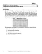
product family include the TPS54311, TPS54312, TPS54313, TPS54314, TPS54315, and
TPS54316. These devices can deliver 3 A of continuous output current from an input
voltage of 3 V to 6 V. The output voltage of these devices is fixed by the internal circuitry,
and is available in 0.9-V, 1.2-V, 1.5-V, 1.8-V, 2.5-V, and 3.3-V options.
Contents
Introduction ..........................................................................................................................................2
Step One: Select a Switching Frequency............................................................................................3
Step Two: Select the Input Filter Components...................................................................................4
Input Decoupling Capacitor.............................................................................................................4
Bulk Input Capacitor .......................................................................................................................4
Step Three: Select the Output Filter Components .............................................................................6
Inductor Selection...........................................................................................................................6
Capacitor Selection.........................................................................................................................7
Multiple Output Capacitors..............................................................................................................8
Description of Capacitor Selection Graphs......................................................................................8
Step Four : Select the Bias and Bootstrap Capacitors....................................................................11
Step Five : Select a Slow Start Time .................................................................................................11
Layout Considerations.......................................................................................................................12
Figures
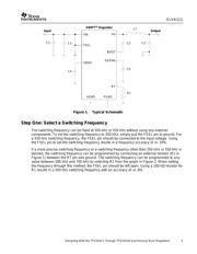
Figure 1.Typical Schematic.................................................................................................................3
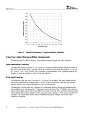
Figure 2.Switching Frequency Trimming Resistor Selection ...........................................................4
Figure 3.Regions of Stability for 2.2-µ
µµ
µH Inductor..............................................................................9
Figure 4.Regions of Stability for 3.3-µ
µµ
µH Inductor..............................................................................9
Figure 5.Regions of Stability for 4.7-µ
µµ
µH Inductor............................................................................10
Figure 6.Regions of Stability for 6.8-µ
µµ
µH Inductor............................................................................10
Figure 7.Regions of Stability for 10-µ
µµ
µH Inductor.............................................................................11
Tables
Table 1. TPS5431x Family Summary..................................................................................................2
SWIFT and PowerPAD are trademarks of Texas Instruments