

herunterladen
Application Report
SLVA105A – February 2002
1
Designing With the TPS54611 Through TPS54616
Synchronous Buck Regulators
Brian King Power Management Products
ABSTRACT
The switcher with integrated FETs (SWIFT™) TPS5461x family of internally compensated
synchronous buck regulators offers a quick and easy solution to many power supply
applications. These devices require a minimum of six additional components. The design
procedure is simple and can be accomplished with the five basic steps outlined in this
application report.
Contents
Introduction..........................................................................................................................................2
Step One: Select a Switching Frequency ...........................................................................................3
Step Two: Select the Input Filter Components...................................................................................4
Input Decoupling Capacitor ............................................................................................................4
Bulk Input Capacitor.......................................................................................................................4
Step Three: Select the Output Filter Components.............................................................................6
Inductor Selection...........................................................................................................................6
Capacitor Selection ........................................................................................................................7
Multiple Output Capacitors .............................................................................................................8
Description of Capacitor Selection Graphs .....................................................................................8
Step Four: Select the Bias and Bootstrap Capacitors.....................................................................11
Step Five: Select a Slow Start Time..................................................................................................11
Layout Considerations.......................................................................................................................12
Figures
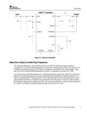
Figure 1. Typical Schematic ............................................................................................................... 3
Figure 2. Switching Frequency Trimming Resistor Selection..........................................................4
Figure 3. Regions of Stability for 2.2-µH Inductor............................................................................. 9
Figure 4. Regions of Stability for 3.3-µH Inductor............................................................................. 9
Figure 5. Regions of Stability for 4.7-µH Inductor........................................................................... 10
Figure 6. Regions of Stability for 6.8-µH Inductor........................................................................... 10
Figure 7. Regions of Stability for 10-µH Inductor............................................................................ 11
Tables
Table 1. TPS5461x Family Summary.................................................................................................. 2
Table 2. Internally Fixed Slow Start Times ......................................................................................12
Table 3. Externally Programmed Slow Start Coefficients............................................................... 12
SWIFT is a trademark of Texas Instruments