

herunterladen

Application Report
SLVA107 – October 2001
1
Designing for Small-Size, High-Frequency Applications
Using TPS546xx DC/DC Converters
Rais Miftakhutdinov High Performance Analog
Power Management Products
ABSTRACT
This application report describes the design procedure for a small-size, high-frequency
application using SWIFT synchronous buck regulators. It shows that the compensation
circuitry of the regulators, with the minimum size output filter and fast transient response,
provides the 150-kHz unity gain bandwidth of the open feedback loop. The design is
illustrated by the 6-A DDR memory, V
TT
tracking regulator TPS54672. The regulator
occupies only 1.33” x 0.445” x 0.3” board space including input and output filters. The
schematic, bill of materials, and main performance curves complete the evaluation of the
design example.
Contents
Introduction .............................................................................................................................................2
SWIFT Family of Synchronous Buck Regulators.................................................................................3
Design Procedure ...................................................................................................................................4
Evaluation Module TPS54672EVM - 200 .............................................................................................10
Schematic and Bill of Materials .......................................................................................................10
Main Waveforms and Performance Curves ....................................................................................12
Conclusion ............................................................................................................................................18
References.............................................................................................................................................18
Figures
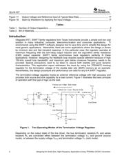
Figure 1. Two Operating Modes of the Termination Voltage Regulator ...................................................2
Figure 2. TPS54672 Block Diagram .........................................................................................................3
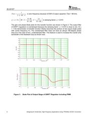
Figure 3. Bode Plot of Output Stage of SWIFT Regulator Including PWM...............................................6
Figure 4. Sum (A(f) = Apt(f) + AEA(f)) of Gains of Regulator Output Stage and Error Amplifier ..............7
Figure 5. Type 3 Compensation ...............................................................................................................7
Figure 6. Overall Feedback Loop Bode Plots...........................................................................................9
Figure 7. Evaluation Module TPS54672EVM-200..................................................................................10
Figure 8. Electrical Schematic of Evaluation Module TPS54672EVM-200 ............................................11
Figure 9. Switching and Output/Input Ripple Waveforms.......................................................................12
Figure 10. Line and Load Regulation ..................................................................................................13
Figure 11. Power Losses Inside the Package .....................................................................................13
Figure 12. Efficiency Curves at the Source Mode ...............................................................................14
Figure 13. Two Types of Overcurrent Protection.................................................................................15
Figure 14. Load Current Transient Response .....................................................................................15
Figure 15. Expanded Load Current Transient Waveforms ..................................................................16
Figure 16. Output Voltage Response to the Reference Voltage Step Transient .................................16
SWIFT is a trademark of Texas Instruments