
herunterladen

APPLICATION NOTE
TSM101 IN S.M.P.S
AN916/0299
by G. AUGUSTONI
®
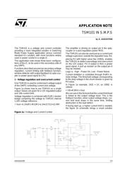
The TSM101 is a voltage and current controller
providing a more integrated solution in Switching
Mode Power Supply application versus common
standard ICs solution, with more functions widely
used in power control in a single IC.
This application note shows three basic configura-
tions of the IC, to be used in the secondary side of
any SMPS.
Functions described are precise secondary voltage
regulation, current limiting with foldback function,
window detector with output feedback to opto-cou-
pler or power good signal to CPU.
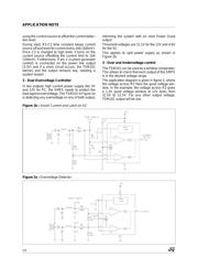
1 - Voltage regulation and overcurrent control
One TSM101 is used to control each voltage output
of the SMPS controlling current and voltage.
Figure 1a shows how to use TSM101 on a single
output. Values are given for a 12V regulated output
and 10A current limit.
Voltage regulation is achieved with R2/R1 resistor
bridge comparing the voltage to TSM101 internal
1.24V voltage reference.
• Vout =1.24x(R1+R2)/R1=1.24x117/12=12.09V
The amplifier is driving on output pin 6 the opto-
coupler or a post regulation power MOS.
The TSM101 can also be used just as a current and
voltage supervisor, outside the regulation loop. Re-
placing R2 with higher value like 110KΩ
, enables
the TSM101 to detect overvoltage and overcurrent
on the 12V output. Pin 6 output is then a power
good signal. A pull up resistor on the output pin 6
may be needed.
Logic is : High - Power Ok, Low - Power failure.
Current limitation is controlled through R4/R3 re-
sistor bridge. The threshold voltage corresponding
to the drop voltage in the shunt resistor is given by
R4 value.
In Figure 1a example, 1KΩ = 1V, so 100Ω is
100mV.
• Vth=R3/R4 x Vout
We can see in this formula that the current limit level
is linked to the output voltage level. This is the
foldback function, when output voltage drops, cur-
rent limit level drops in the same time, limiting
destruction in the load defect.
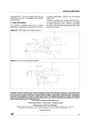
If during start up, a higher current limit is needed,
the figure 1b schematic brings a smart solution
Figure 1a : Voltage and Current Control
1/3