

herunterladen

Application Report
SLVA385–March 2012
Monitoring Voltage, Current, and Temperature Using the
UCD90xxx Devices
Michael Vega ............................................................................... PMP-LP Supervisors and Sequencers
ABSTRACT
This application report discusses how to set up the UCD90xxx (excluding the UCD908x) Sequencer
integrated circuits so that they can measure voltages which can represent voltage, current, and
temperature measurements of power supplies. Note that although monitoring is essential for sequencing,
this document does not cover setting up for sequencing.
The example discussed in this document strongly focuses on using the UCD9012x evaluation module
(EVM), but the concepts discussed apply to any particular system in which a UCD90xxx device is
embedded. From a setup point of view, all configurations are made using the Fusion Digital Power™
designer software. The commands that system designers need to implement in their system to interact
with the UCD9012x using PMBus in the application circuit are discussed in the last section of this report.
Note that in the example used, it is recommended that jumpers J22, J25, J30, and J33 are removed.
These connections are specific for power supply margining which is discussed in another document
(SLVA375).
Contents
1 Setting Up a Rail for Voltage Monitoring ................................................................................. 2
2 Setting Up a Rail for Current Monitoring ................................................................................. 6
3 Setting Up a Rail for Temperature Monitoring .......................................................................... 9
4 Using PMBus to Read Measurements .................................................................................. 10
List of Figures
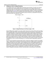
1 Voltage Monitoring Circuit (Power Supply > 2.5V) ..................................................................... 2
2 Pin Assignment Screen Within the Configure Function................................................................ 3
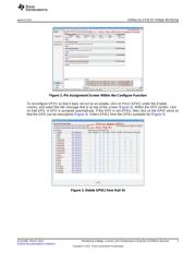
3 Delete GPIO1 from Rail #1 ................................................................................................ 3
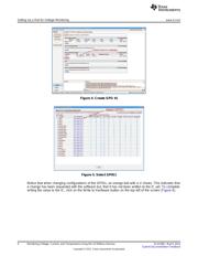
4 Create GPO #1.............................................................................................................. 4
5 Select GPIO1................................................................................................................ 4
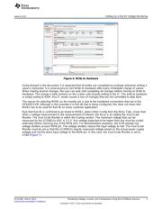
6 Write to Hardware........................................................................................................... 5
7 Set Vout Scale Monitor..................................................................................................... 6
8 Voltage Measurement for Rail #1......................................................................................... 6
9 Current Monitoring Circuit Using the INA196............................................................................ 7
10 Rail #1 Current Setting..................................................................................................... 8
11 Select MON3 for Current Monitoring ..................................................................................... 8
12 Rail #1 Voltage and Current Measurements ............................................................................ 9
13 Temperature Monitoring Circuit in UCD9012x EVM.................................................................... 9
14 Rail #1 – Voltage, Current and Temperature Measurements ....................................................... 10
Fusion Digital Power is a trademark of Texas Instruments.
1
SLVA385–March 2012 Monitoring Voltage, Current, and Temperature Using the UCD90xxx Devices
Submit Documentation Feedback
Copyright © 2012, Texas Instruments Incorporated
Verzeichnis