


herunterladen
IS31LT3938 DC-DC DEMO Board Guide
Integrated Silicon Solution, Inc. – www.issi.com 1
R1.0, 9/29/2012
Description
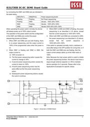
IS31LT3938 LED driver IC is a peak current detection
buck converter which operates in constant off time
mode. It operates over a very wide input voltage supply
range of 6VDC to 450VDC or 110VAC/220VAC.
IS31LT3938 incorporates the special feature of power
sequencing by detecting OFF-ON cycles of the main
power switch. When the switch is cycled within a 2
second period (typical) the device automatically
switches the power sequencing level to the next step.
As a result, power sequencing can be achieved without
replacing any wiring in the original system. There are
multiple modes of power sequencing that the user may
configure, 2 steps or 3 steps, as well as different levels
of power sequencing via the external pins DIM1 and
DIM2.
Features
User configurable power sequencing levels
3% output current accuracy
Over current, voltage and temperature protection
High efficiency (typical up to 95%)
Wide input voltage range: 6VDC~450VDC or
85Vac~ 265Vac
Linear and PWM dimming
Very few external components
Applications
DC/DC or AC/DC LED driver applications
Signal and decorative LED lighting
backlighting LED driver
Order information
Part Number Package Type
IS31LT3938-GRLS2-EBDCDC SOP-8
Quick Start
Recommended Equipment
60VDC power supply
LED array(1W LED, 12 in series,6 in parallel)
Main power switch
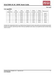
Recommended Input and Output Ratings
Input: 48VDC
Output: 12LEDs in series/2A
Note: The input voltage must be 3V higher than the output
voltage(total Vf).
Absolute Maximum Ratings
≤ 60VDC
≤ 42V Vout (Total Vf)
Caution: Do not exceed the conditions listed above, otherwise
the board will be damaged or the output will be changed.
Procedure
The IS31LT3938 DEMO Board is fully assembled and
tested. Follow the steps listed below to verify board
operation.
Caution: Do not turn on the power supply until all
connections are completed.
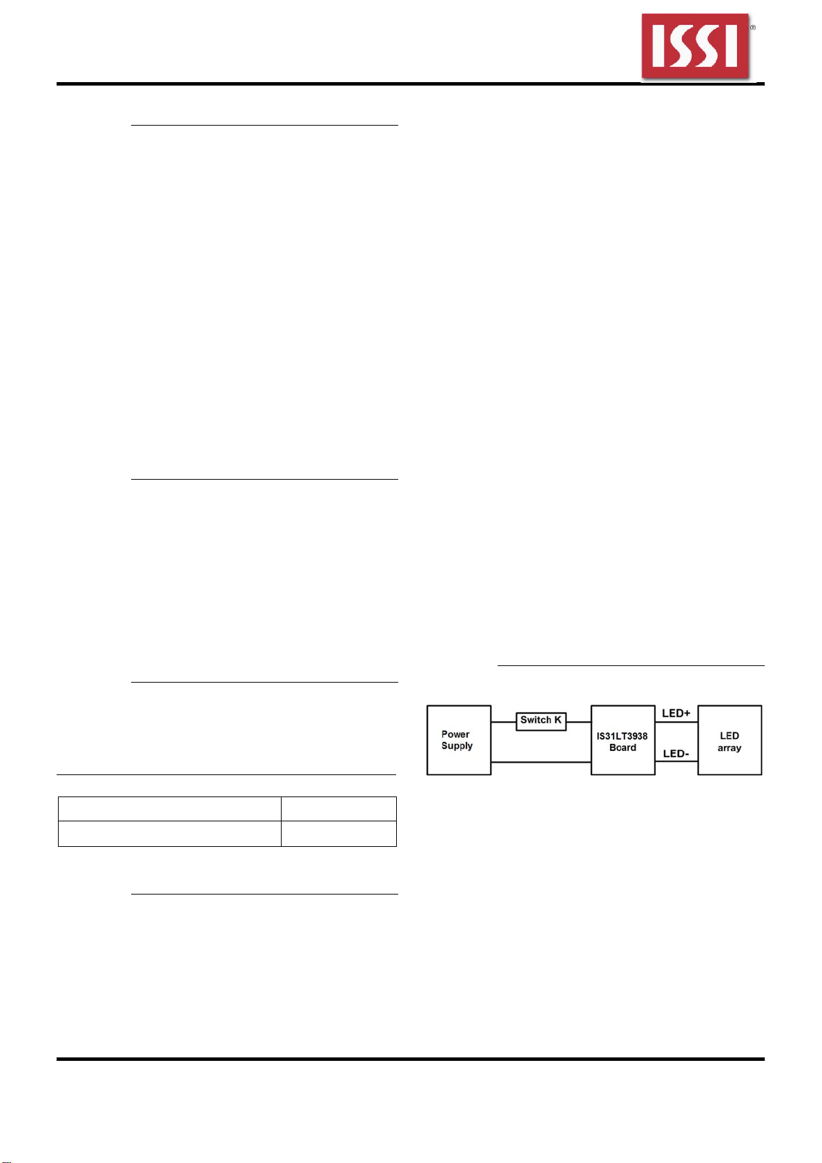
1) Connect the positive terminal of the power supply
to the DC+ of the board and the negative terminal
of power supply to the DC- of the board.
2) Connect the negative of the LED panel (LED
arrays) to the LED- terminal.
3) Connect the positive of the LED panel (LED arrays)
to the LED+ terminal.
4) Turn on the power supply and the LED panel (LED
arrays) will be light.
Detailed description
Power sequencing
The action of the main power switch can be divided into
two types. The first is “normal switch operation”
wherein the switch is toggled from ON to OFF,
remaining OFF for longer than 2 seconds (typical). The
other is “power sequencing action” wherein the switch
is toggled from ON to OFF and back ON within 2
seconds (typical).
When the device experiences normal switch operation,
it merely powers on in the first state when the power
switch is toggled to ON, and the device turns off when
the main power switch is changed to OFF.
Power sequencing output current levels are configured
Verzeichnis