

AN-854
APPLICATION NOTE
One Technology Way • P.O. Box 9106 • Norwood, MA 02062-9106, U.S.A. • Tel: 781.329.4700 • Fax: 781.461.3113 • www.analog.com
Rev. A | Page 1 of 12
Sensor PCB Design Guidelines for the
AD7142 and AD7143 Capacitance-to-Digital Converters
by Susan Pratt
INTRODUCTION SENSOR TYPES AND SIZES
The AD7142 and AD7143 are integrated capacitance-to-digital
converters (CDC) with on-chip environmental calibration for
use in systems requiring a novel user input method. The
AD7142 and AD7143 can interface to external capacitance
sensors implementing functions such as capacitive buttons,
sliders, or scroll wheels.
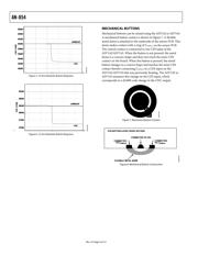
Table 1 shows the recommended minimum, typical, and
maximum sensor sizes, and the typical bulk capacitance for a
range of sensor types. The total area of the sensor, rather than
the exact dimensions, is of greatest importance. A sensor with a
large area provides a large electric field with which the user can
interact, and therefore, gives the greatest response when activated.
The minimum sensor sizes are driven by the need to obtain an
adequate sensor response. It is possible to use different shapes
that may be below the minimum sensor size in one dimension,
provided the total area of the sensor is sufficient to obtain a
good response.
The sensors are implemented as individual elements on a PCB
with all sensors for a particular design, as well as the AD7142 or
AD7143 on the same PCB. Sensor designs can be customized to
suit each customer’s individual requirements. The customer can
specify the type of sensors, the layout, and the dimensions. The
AD7142 and AD7143 can cater to nonstandard shapes, such as
curved sensors, giving customers full flexibility in their product
designs.
The maximum sensor size is dictated by the sigma-delta (Σ-Δ)
converter and offset digital-to-analog converters (DACs) on the
AD7142 and AD7143.
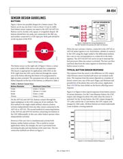
Figure 1 shows C
BULK
, the capacitance
associated with the sensor. When the sensor is active, the user
interferes with the fringe field, CIN (CIN << C
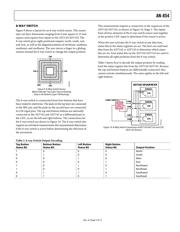
The maximum number of sensors implemented using one
AD7142 or one AD7143 depends on the combination of sensors
in the design. A slider requires eight inputs to the AD7142 or
AD7143, a button requires one input, and an 8-way switch
requires four inputs. Combinations of sensors can be imple-
mented using one AD7142 or one AD7143.
BULK
). If the
sensor is too large, its bulk capacitance value swamps the
converter, and the offset DACs do not have sufficient range to
offset this capacitance. The maximum capacitance value for
which the offset DAC can compensate is ±20 pF.
PLASTIC OVERLAY
SENSOR BOARD
C
BULK
CIN
CAPACITIVE SENSOR
0
6182-001
Figure 1. Sensor Bulk Capacitance and Fringe Capacitance
Table 1. Sensor Sizes and Bulk Capacitance
Sensor Type Minimum Size Typical Size Maximum Size Typical Bulk Capacitance
Button 5 mm diameter 8 mm diameter 15 mm 4 pF
2-Way Switch 4 mm × 8 mm 5 mm × 10 mm 8 pF
8-Way Switch 8 mm × 8 mm 15 mm × 15 mm 4 pF per element
Slider 25 mm × 4 mm 40 mm × 10 mm 60 mm × 20 mm 4 pF per element
Wheel 20 mm diameter 30 mm diameter 50 mm diameter 4 pF per element
Key Pad 1 row × 1 column 12 keys, 3 rows × 4 columns 36 keys, 6 rows × 6 columns 5.4 pF to 9.6 pF per key
Verzeichnis