
herunterladen

AD8450-EVALZ/ADP1972-EVALZ User Guide
UG-845
One Technology Way • P. O. Box 9106 • Norwood, MA 02062-9106, U.S.A. • Te l: 781.329.4700 • Fax: 781.461.3113 • www.analog.com
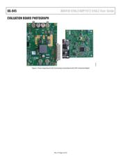
AD8450/ADP1972 Battery Testing and Formation Evaluation Board
PLEASE SEE THE LAST PAGE FOR AN IMPORTANT
WARNING AND LEGAL TERMS AND CONDITIONS.
Rev. 0 | Page 1 of 33
FEATURES
Fully functional Li-Ion cell formation and testing similar to
real-world manufacturing equipment
Ability to charge and discharge batteries under constant
current (CC) and constant voltage (CV) control
Energy recycling from discharging battery into dc bus
Full featured system evaluation board based on the
AD8450 and ADP1972
PC software for control and monitoring of system
parameters
Compatible with the system demonstration platform,
SDP-S (EVAL-SDP-CS1Z)
EQUIPMENT NEEDED
Bench power supply, 12 V dc (current depending on desired
battery charge rate)
Test batter y
EVALUATION KIT CONTENTS
Analog control board
Power stage board
SDP-S board for data transfer to PC
Standard USB A to Mini-B USB cable
Printed user guide
Evaluation kit software CD
Business card with Analog Devices, Inc., website address for
software and documentation
HARDWARE REQUIREMENTS
Bench power supply, 12 V dc (current depending on desired
battery charge rate)
Test battery or electronic load
PC running Windows 7
WARNING
When testing this system with lithium-ion (Li-Ion) batteries,
take care not to overcharge or overdischarge the batteries, or to
sink/source more than the maximum current recommended by
the manufacturer of the battery. Exceeding these ratings not
only damages the battery, but can also cause it to explode or
catch fire.
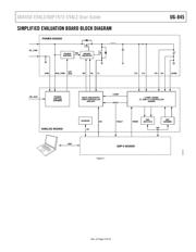
GENERAL DESCRIPTION
The AD8450-EVALZ/ADP1972-EVALZ evaluation kit is a good
starting point for users building battery formation and test
equipment based on the Analog Devices AD8450 precision
analog front end and controller and the ADP1972 buck or boost
pulse-width modulation (PWM) controller. The system includes
an analog control board and a power stage board.
In addition to the AD8450 and ADP1972, the analog control
board also includes an AD5689R 16-bit, precision digital-to-
analog converter (DAC) to set the current and voltage set points,
and an AD7173-8 24-bit, Σ-Δ analog-to-digital converter (ADC)
to monitor the battery voltage and current.
The board includes built-in voltage regulators so that it can be
powered either from the power stage board or directly from a
12 V dc through a screw terminal connector.
The analog control board connects to the Analog Devices
system demonstration platform—serial (SDP-S) board through
a 120-pin connector. The SDP-S board connects to the user
interface software through the USB port, allowing the user to
set the current and voltage set point as well as the mode of
operation (charge/discharge). In addition, the user can monitor
the battery voltage and current by reading the data output from
the AD7173-8.
The analog control board connects to the power stage board
through a 32-pin header. This modular approach allows the
user to design and test their own power stage boards, designed
for the current output range in their end applications, with the
analog control board of this reference design.
The power stage board supports charge and discharge currents
of up to 20 A. It includes the power MOSFETs, inductor, and
input and output capacitors required to implement a buck or
boost regulator, depending on the operating mode.
Full specifications on the ADP1972 and AD8450 are available in
the product data sheets, which should be consulted in conjunction
with this user guide when working with the evaluation kit.
The AD8451 can also be installed in the AD8450 socket with
minimal changes.