
herunterladen
Evaluation Board User Guide
UG-889
One Technology Way • P. O. Box 9106 • Norwood, MA 02062-9106, U.S.A. • Te l : 781.329.4700 • Fax: 781.461.3113 • www.analog.com
Evaluation Board for Single Differential Amplifiers
Offered in 16-Lead LFCSP Packages
PLEASE SEE THE LAST PAGE FOR AN IMPORTANT
WARNING AND LEGAL TERMS AND CONDITIONS.
Rev. A | Page 1 of 4
FEATURES
Enables quick breadboarding/prototyping
User defined circuit configuration
Edge mounted SMA connector provisions
Easy connection to test equipment and other circuits
RoHS compliant
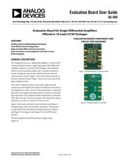
GENERAL DESCRIPTION
The Analog Devices, Inc., differential amplifier, 16-lead LFCSP
evaluation board evaluates single, high speed, fully differential
amplifiers offered in 16-lead LFCSP packages. The evaluation
board is a bare board that enables users to quickly prototype a
variety of single op amp circuits, which minimizes risk and
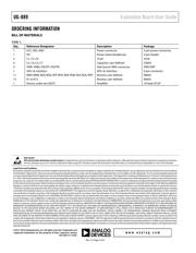
reduces time to market. Figure 1 shows the component side of
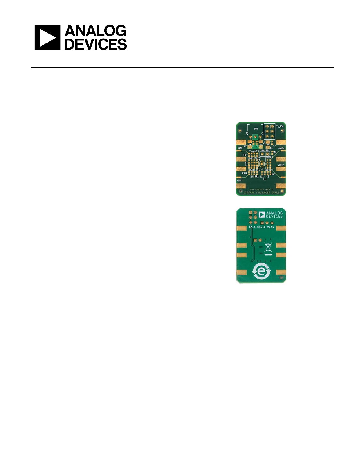
the bare evaluation board. Figure 2 shows the circuit side of the
bare evaluation board.
The 6-layer evaluation board accepts SMA edge-mounted
connectors on the inputs and outputs for efficient connection to
test equipment or other circuitry. The ground plane, component
placement, and supply bypassing minimize parasitic inductance
and capacitance. The evaluation board components are primarily
SMT 0603 case size, with the exception of the electrolytic bypass
capacitors (C1 and C2), which are 3528 case size.
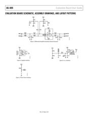
Figure 3 shows the evaluation board schematic and Figure 4
through Figure 6 show the interface schematics. The printed
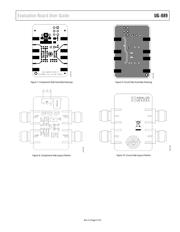
circuit board (PCB) assembly drawings are shown in Figure 7
and Figure 9. See Figure 8 and Figure 10 for the PCB layout
patterns.
The layout pattern for the PCB is shown in Figure 8 and
Figure 10.
EVALUATION BOARD COMPONENT AND
CIRCUIT SIDE DIAGRAMS
Figure 1. Evaluation Board, Component Side
Figure 2. Evaluation Board, Circuit Side
13587-001
13587-002
Verzeichnis