

Evaluation Board User Guide
UG-339
One Technology Way • P. O. Box 9106 • Norwood, MA 02062-9106, U.S.A. • Te l: 781.329.4700 • Fax: 781.461.3113 • www.analog.com
ADL5304 Evaluation Board User Guide
PLEASE SEE THE LAST PAGE FOR AN IMPORTANT
WARNING AND LEGAL TERMS AND CONDITIONS.
Rev. 0 | Page 1 of 16
FEATURES
4-layer printed circuit board (PCB), 53 mm × 72 mm form factor
Resistor programmable log slope and intercept
Single-or dual-supply operation
Full two argument logarithmic computation
On-board precision 100 nA reference
Optimized for very fast response at all input currents
Overall bandwidth of >4 MHz for inputs >1 μA
Bandwidth: 25 kHz at input of 1 nA and 350 kHz at 10 nA
10 decades of input range: 1 pA to 10 mA
Law conformance: ±0.25 dB from 100 pA to 100 μA
Log ratio or fixed-intercept operation
On-board precision 1.5 V and 2.0 V voltage references
Adaptive photodiode (PD) bias for low dark current
Default log slope of 10 mV/dB at VLOG pin
GENERAL DESCRIPTION
This user guide refers to the ADL5304 evaluation board, which
allows users to connect the ADL5304 precision log amplifier to
current sources with simple SMA connections or, with modifica-
tion of the default configuration, to mount a photodiode to the
INUM input for optical power level applications.
The ADL5304 evaluation board is laid out to minimize errors
due to leakage into the sensitive INUM and IDEN nodes
through driven guards.
Slope and logarithmic intercept are programmable through
on-chip resistors and can be further optimized for specific
applications using external resistors. Additional components
can be added to optimize filtering for specific applications.
Adaptive photodiode bias is available using the IMON output to
optimize photodiode response and dark current.
Full details about the part are available in the ADL5304 data sheet,
which should be consulted when using the ADL5304-EVALZ.
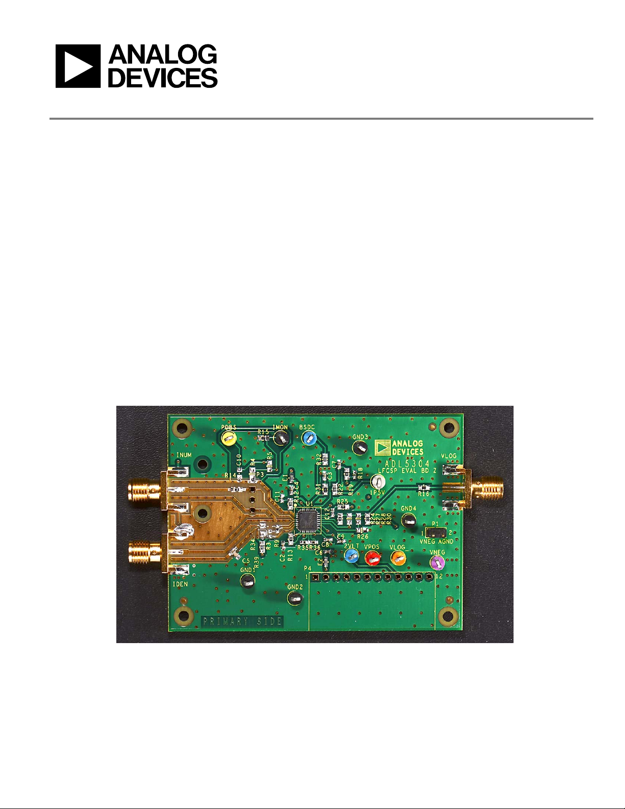
Figure 1. Top View of ADL5304 Evaluation Board
10321-001
Verzeichnis