
herunterladen
Software User Guide
UG-005
One Technology Way • P. O. Box 9106 • Norwood, MA 02062-9106, U.S.A. • Te l: 781.329.4700 • Fax: 781.461.3113 • www.analog.com
ADP8860 Software User Guide
INTRODUCTION
This user guide describes the functionality of the Analog
Devices, Inc., ADP8860 and provides software development
guidelines. The ADP8860 communicates with an external
processor using an I
2
C interface and an interrupt line (nINT).
The processor sends initialization and activation commands
to the ADP8860, which acts as a slave device.
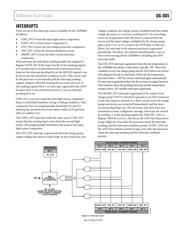
The interrupt line, from the ADP8860 to the processor, is used
to indicate a failure condition, such as a thermal shutdown or
an overvoltage and LED/output short circuit, or to indicate a
light level threshold has been crossed. All interrupt sources are
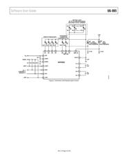
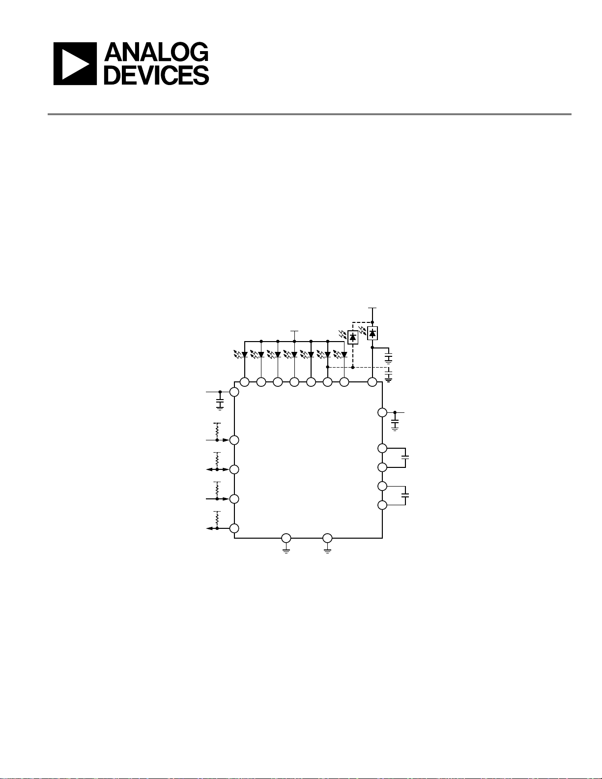
maskable. Refer to Figure 1 for a typical application diagram.
Figure 2 shows a schematic with keypad light control.
The interrupt line is active low; each interrupt source has an
individual masking bit. The processor can reset the ADP8860
anytime by pulling the nRST line low; this operation reinitia-
lizes the ADP8860 at the default state and places the device
in standby mode.
V
Rev. 0 | Page 1 of 44
08158-001
D3
D1
E3
D2
E4
D3
D4
D4
C4
D5
B4
D6/
CMP_IN2
B3
D7
C3
CMP_IN
V
OUT
OPTIONAL
PHOTOSENSOR
PHOTOSENSOR
ALS
0.1µF
0.1µF
E1
VDDIO
nRST
C2
VDDIO
SDA
E2
VDDIO
SCL
D2
VDDIO
nINT
A3
V
IN
1µF
A4
GND1
D1
GND2
B1
C2+
B2
C2–
C2
1µF
A1
C1+
C1
C1–
C1
1µF
V
OUT
A2
1µF
ADP8860
Figure 1. Typical Application Schematic with Optional Second Photo Diode
Verzeichnis