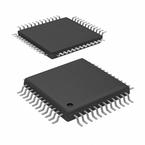
herunterladen

User's Guide
SLAU150 – December 2004
ADS7881/ADS7891EVM
This users guide describes the characteristics, operation, and use of the
ADS7881/ADS7891 12-Bit/14-Bit, parallel, analog-to-digital converter evaluation mod-
ule. A complete circuit description, as well as schematic diagram, layout and bill of
materials, are included.
Contents
1 Related Documentation from Texas Instruments ............................................... 1
2 EVM Overview ...................................................................................... 2
3 Introduction .......................................................................................... 2
4 Analog Interface .................................................................................... 2
5 Digital Interface ..................................................................................... 4
6 Power Supplies ..................................................................................... 6
7 Using the EVM ...................................................................................... 6
Appendix A ADS7881EVM/ADS7891EVM Bill of Materials ........................................ 8
Appendix B ADS7881EVM/ADS7891EVM Layout ................................................ 10
Appendix C ADS7881EVM/ADS7891EVM Schematic ............................................ 14
List of Figures
1 ADS7881 Input Buffer Circuit ..................................................................... 3
2 Decoding Control Signals Using the Address Bus ............................................. 7
B-1 Top Layer – Layer 1 .............................................................................. 10
B-2 Ground Plane – Layer 2 .......................................................................... 11
B-3 Power Plane – Layer 3 ........................................................................... 12
B-4 Bottom Layer – Layer 4 .......................................................................... 13
List of Tables
1 Analog Input Connector ............................................................................ 2
1 Analog Input Connector ............................................................................ 3
2 Solder Short Jumper Setting ...................................................................... 4
3 Pinout for Parallel Control Connector P2 ........................................................ 4
4 Jumper Settings ..................................................................................... 5
5 Data Bus Connector P3 ............................................................................ 5
6 Pinout for Converter Control Connector J3 ..................................................... 6
7 Power Supply Test Points ......................................................................... 6
8 Power Connector, J1, Pin Out .................................................................... 6
A-1 Bill of Materials ...................................................................................... 8
ADS7881/ADS7891EVMSLAU150 – December 2004 1
Verzeichnis
- ・ Blockdiagramm on Seite 14
- ・ Anwendungsbereich on Seite 19


