


herunterladen
Semiconductor Components Industries, LLC, 2004
August, 2004 − Rev. 0
1 Publication Order Number:
AND8181/D
AND8181/D
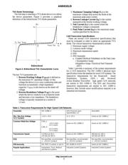
TVS Diode Selection
Guidelines for the CAN Bus
Prepared by: Jim Lepkowski, Paul Lem
Introduction
The Controller Area Network (CAN) is a serial
communication protocol designed for providing reliable
high speed data transmission in harsh environments. This
document provides guidelines to select Transient Voltage
Suppression (TVS) diodes to protect CAN data bus lines.
TVS diodes provide a low cost solution to conducted and
radiated Electromagnetic Interference (EMI) and
Electrostatic Discharge (ESD) noise problems. The noise
immunity level and reliability of CAN transceivers can be
easily increased by adding external TVS diodes to prevent
transient voltage failures.
NUP2105L CAN Bus TVS Diode Array
The NUP2105L provides a transient voltage suppression
solution for CAN data communication lines. The
NUP2105L is a dual bidirectional TVS device in a compact
SOT−23 package. This device is based on Zener technology
that optimizes the active area of a PN junction to provide
robust protection against transient EMI surge voltage and
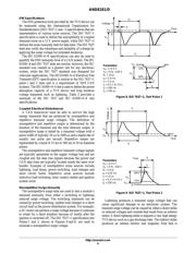
ESD. Figure 1 provides a circuit diagram of the NUP2105L.
The NUP2105L has been tested to EMI and ESD levels
that exceed the specifications of popular high speed CAN
networks. Listed below is a summary of the
NUP2105L’s EMI and ESD specifications.
• 350 W Peak Power Dissipation per line, (8 x 20 s)
• Human Body Model ESD protection ≥ 16 kV
• IEC−61000−4−2 ESD level ≥ 30 kV for contact
discharge
• ISO 7637−1, nonrepetitive EMI surge pulse 2, 9.5 A
(1 x 50 s)
• ISO 7637−3, repetitive Electrical Fast Transient (EFT)
EMI surge pulses, 50 A (5 x 50 ns)
• IEC 61000−4−5 lightning and load switch immunity,
10 A (8 x 20 s)
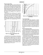
The NUP2105L uses silicon semiconductor technology to
offer distinct advantages over alternative TVS protection
devices such as MOVs and choke filters. A TVS diode
provides a fast response time, low line capacitance and low
clamping voltage. The NUP2105L has a time response time
of less than 1.0 ns and is able to clamp fast surge transient
voltages before damage can occur. The silicon design has a
line capacitance less than 30 pF, which is required for the
high 1.0 MHz data transmission rate. The voltage clamping
limit of the device, defined by the 8 x 20 s exponential
waveform, is approximately equal to 42 V for a surge
current of 10 A. The low clamping voltage ensures that the
transient sure voltage will not exceed the CAN transceiver’s
maximum voltage specification for the CAN_H and
CAN_L data lines.
Figure 1. NUP2105L Bidirectional TVS/ESD
Protection Device
PIN 1
PIN 3
PIN 2
1
2
3
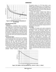
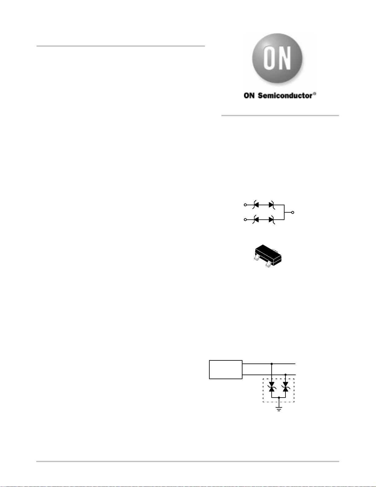
Figure 2 provides an example of a typical CAN bus
protection circuit. The circuit provides protection for the
CAN_H and CAN_L data lines by clamping the surge
voltage to a level that will not damage the CAN transceiver.
Further details on CAN protection circuits are provided in
reference (1).
Figure 2. High−Speed and Fault Tolerant CAN TVS
Protection Circuit
CAN
Transceiver
CAN_H
CAN_L
NUP2105L
CAN Bus
APPLICATION NOTE
http://onsemi.com
Verzeichnis