


herunterladen
AP1513
Document number: DS31053 Rev. 5 - 2
1 of 9
www.diodes.com
December 2017
© Diodes Incorporated
AP1513
PWM CONTROL 2A STEP-DOWN CONVERTER
Description
AP1513 consists of step-down switching regulator with PWM control.
These devices include a reference voltage source, oscillation circuit,
error amplifier, and internal PMOS.
AP1513 provides low-ripple power, high efficiency, and excellent
transient characteristics. The PWM control circuit is able to vary the
duty ratio linearly from 0 up to 100%. This converter also contains an
error amplifier circuit as well as a soft-start circuit that prevents
overshoot at startup. An enable function, an over current protect
function and a short circuit protect function are built inside, and when
OCP or SCP happens, the operation frequency will be reduced from
300kHz to 30kHz. Also, an internal compensation block is built in to
minimum external component count.
With the addition of an internal P-channel Power MOS, a coil,
capacitors, and a diode connected externally, these ICs can function
as step-down switching regulators. They serve as ideal power supply
units for portable devices when coupled with the SO-8 mini-package,
providing such outstanding features as low current consumption.
Since this converter can accommodate an input voltage up to 18V, it is
also suitable for the operation via an AC adapter.
Features
Input Voltage: 3.6V to 18V
Output Voltage: 0.8V to V
CC
Duty Ratio: 0% to 100% PWM Control
Oscillation Frequency: 300kHz Typ
Soft-start, Current Limit, Enable Function
Thermal Shutdown Function
Built-in Internal SW P-channel MOS
Totally Lead-Free & Fully RoHS Compliant (Notes 1 & 2)
Halogen and Antimony Free.“Green” Device (Note 3)
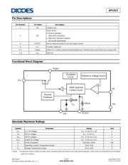
Pin Assignments
(Top View)
1
2
3
4
8
7
6
5
FB
Output
OCSET
AP1513
Output
EN
V
SS
V
SS
V
CC
SO-8
Applications
PC Motherboard
LCD Monitor
Graphic Card
DVD-Video Player
Telecom Equipment
ADSL Modem
Printer and Other Peripheral Equipment
Microprocessor Core Supply
Networking Power Supply
Notes: 1. No purposely added lead. Fully EU Directive 2002/95/EC (RoHS) & 2011/65/EU (RoHS 2) compliant.
2. See http://www.diodes.com/quality/lead_free.html for more information about Diodes Incorporated’s definitions of Halogen- and Antimony-free,"Green"
and Lead-free.
3. Halogen- and Antimony-free "Green” products are defined as those which contain <900ppm bromine, <900ppm chlorine (<1500ppm total Br + Cl) and
<1000ppm antimony compounds.
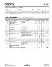
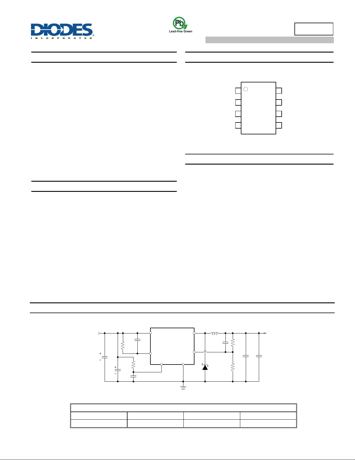
Typical Applications Circuit
AP1513
+
-
V
SS
EN
C
C
R
A
R
B
D1
SBR2U30P1
FB
Vcc
Output
CVcc
V
OUT
= 5V/2A
V
IN
R
OCSET
OCSET
C
OUT
C
IN
Optional
C
OCSET
C
EN
R
EN
Option
100K
L1
33µH
6.8K
1.3K
3K
0.1µF
+
-
C
0.1µF
470µF
470µF
0.1µF
V
IN
= 12V, I
MAX
= 2A
V
OUT
2.5V
3.3V
5V
L1 Value
22µH
27µH
33µH
Note: V
OUT
=V
FB
x (1+R
A
/R
B
)
R
B
=0.7kΩ to 5kΩ
Verzeichnis
- ・ Konfiguration des Pinbelegungsdiagramms on Seite 1 Seite 2
- ・ Abmessungen des Paketumrisses on Seite 8
- ・ Paket-Footprint-Pad-Layout on Seite 8
- ・ Teilenummerierungssystem on Seite 7
- ・ Markierungsinformationen on Seite 7
- ・ Blockdiagramm on Seite 2
- ・ Typisches Anwendungsschaltbild on Seite 1
- ・ Beschreibung der Funktionen on Seite 6 Seite 7
- ・ Technische Daten on Seite 2
- ・ Anwendungsbereich on Seite 1
- ・ Elektrische Spezifikation on Seite 3 Seite 4 Seite 5