
herunterladen

Issue 4 – May 2010 www.diodes.com
© Diodes Incorporated, 2010
AP8802EV1 USER GUIDE
DESCRIPTION
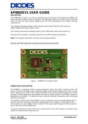
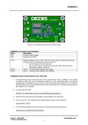
The AP8802EV1, Figure 1, is a PCB constructed using an FR4 base for evaluating the AP8802 LED
driver with internal switch in SOP 8L package. The evaluation board can be used to drive an external
choice of LEDs; the total forward voltage across the LEDs depending on the number and type
connected. [1].
The suggested operating voltage for the evaluation board ranges from 8V to 45V maximum.
Higher voltage means lower supply current.
The nominal current for the evaluation board is set at 700mA with a 0R3 sense resistor, R1.
Test point CTRL provides a connection point for DC or PWM dimming and shutdown.
Note: The evaluation board does not have reverse polarity protection
Warning: with 700A output, the connected LED will be hot and very bright
Figure 1: AP8802EV1 evaluation board
AP8802 DEVICE DESCRIPTION
The AP8802 is a step-down DC/DC converter designed to drive LEDs with a constant current. The
device can drive up to thirteen LEDs, depending largely on the forward voltage of the LEDs, in series
from a voltage source of 8V to 60V. Series connection of the LEDs provides identical LED currents
resulting in uniform brightness and eliminates the need for ballast resistors. The AP8802 switches at
frequencies up to 500kHz. This allows the use of small size external components, hence minimizing
the PCB area needed.
The maximum output current of the AP8802 is set via an external resistor connected between the V
IN
and SET input pins. Dimming is achieved by applying either a DC voltage or a PWM signal at the
CTRL input pin. An input voltage of 0.2V or lower at CTRL shuts down the output at SW and puts the
device into a low-current standby state.
The device includes the output switch and a current sense circuit, which requires an external sense
resistor to set the nominal current up to 1A.
Verzeichnis