

herunterladen

User's Guide
SLUU438–July 2010
bq25050/bq25060EVM
This user's guide describes the features and operation of the bq25050/bq25060EVM Evaluation Module
(EVM). This EVM assists users in evaluating the bq25050 and bq25060 linear battery chargers. The
manual includes the bq25050/bq25060EVM bill of materials, board layout, and schematic.
Contents
1 Introduction .................................................................................................................. 2
1.1 EVM Features ...................................................................................................... 2
1.2 General Description ................................................................................................ 2
1.3 I/O Description ...................................................................................................... 2
1.4 Control and Key Parameters Setting ............................................................................ 3
1.5 Recommended Operating Conditions ........................................................................... 3
2 Equipment .................................................................................................................... 4
2.1 Power Supplies ..................................................................................................... 4
2.2 Loads ................................................................................................................ 4
2.3 Meters ............................................................................................................... 4
2.4 Computer and Interface ........................................................................................... 4
3 Equipment Setup ............................................................................................................ 4
4 Procedure .................................................................................................................... 6
4.1 Charger Operation with Minimum System Voltage Mode .................................................... 6
4.2 Input Current Setting .............................................................................................. 7
4.3 Charger Cut-Off by Thermistor ................................................................................... 7
5 PCB Layout Guideline ...................................................................................................... 8
6 Bill of Materials, Board Layout, and Schematics ........................................................................ 9
6.1 Bill of Materials ..................................................................................................... 9
6.2 Board Layout ...................................................................................................... 10
6.3 Schematic ......................................................................................................... 12
List of Figures
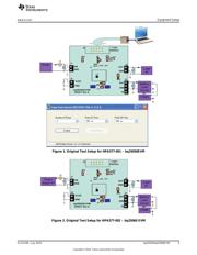
1 Original Test Setup for HPA577-001 – bq25050EVM.................................................................. 5
2 Original Test Setup for HPA577-002 – bq25060 EVM................................................................. 5
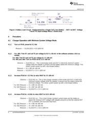
3 Battery Load Circuit – Replacement for a Single Cell Li-Ion Battery → BAT+ to BAT– Voltage Tracks P/S
Input Voltage Minus 1 Diode Drop. ...................................................................................... 6
4 Top Layer................................................................................................................... 10
5 Bottom Layer............................................................................................................... 10
6 Top Assembly.............................................................................................................. 11
7 bq25050/60 EVM Schematic (Sheet 1 of 1) ........................................................................... 12
List of Tables
1 I/O Description............................................................................................................... 2
2 Control and Key Parameters Setting..................................................................................... 3
3 Recommended Operating Conditions.................................................................................... 3
4 Bill of Materials.............................................................................................................. 9
1
SLUU438–July 2010 bq25050/bq25060EVM
Copyright © 2010, Texas Instruments Incorporated
Verzeichnis