


herunterladen
Rc
Rc
Rc
Rc
Rsns
Cc
Cc
Cc
Cc
Cc
100
0.1 µF
4.7 µF
BAT
VC5
VC4
VC3
VC2
VC1
VSS
SCL
SDA
CHG
DSG
REGSRC
REGOUT
SRN
SRP
VC0
CAP1
TS1
Cf
100
0.1 µF
1 µF
Rc
Rf
1M1M
Rc
10k
ALERT
1M
PUSH- BUTTON FOR BOOT
VCC
GPIO
SDA
SCL
VSS
Cc
1 µF
0.1 µF
10 kΩ
PACK +
PACK–
Companion
Controller
Product
Folder
Sample &
Buy
Technical
Documents
Tools &
Software
Support &
Community
bq76920, bq76930, bq76940
SLUSBK2F –OCTOBER 2013–REVISED NOVEMBER 2015
bq769x0 3-Series to 15-Series Cell Battery Monitor Family
for Li-Ion and Phosphate Applications
1 Introduction
1
1.1 Features
– Undervoltage (UV)
• AFE Monitoring Features
– Secondary protector fault detection
– Pure digital interface
• Additional Features
– Internal ADC measures cell voltage, die
temperature, and external thermistor – Integrated cell balancing FETs
– A separate, internal ADC measures pack – Charge, discharge low-side NCH FET drivers
current (coulomb counter)
– Alert interrupt to host microcontroller
– Directly supports up to three thermistors
– 2.5-V or 3.3-V output voltage regulator
(103AT)
– No EEPROM programming necessary
• Hardware Protection Features
– High supply voltage abs max (up to 108 V)
– Overcurrent in discharge (OCD)
– Simple I
2
C™ compatible interface (CRC option)
– Short circuit in discharge (SCD)
– Random cell connection tolerant
– Overvoltage (OV)
1.2 Applications
• Light Electric Vehicles (LEV): eBikes, eScooters, • Battery Backup and UPS Systems
Pedelec, and Pedal-Assist Bicycles
• Wireless Base Station Backup Systems
• Power and Gardening Tools
• 12-V, 18-V, 24-V, 36-V, and 48-V Battery Packs
1.3 Description
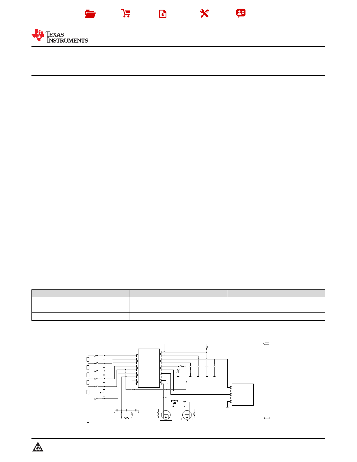
The bq769x0 family of robust analog front-end (AFE) devices serves as part of a complete
pack monitoring and protection solution for next-generation, high-power systems, such as light electric
vehicles, power tools, and uninterruptible power supplies. The bq769x0 is designed with low power in
mind: Sub-blocks within the IC may be enabled/disabled to control the overall chip current consumption,
and a SHIP mode provides a simple way to put the pack into an ultra-low power state.
Device Information
(1)
PART NUMBER PACKAGE BODY SIZE (NOM)
bq76920 TSSOP (20) 6.50 mm × 4.40 mm
bq76930 TSSOP (30) 7.80 mm × 4.40 mm
bq76940 TSSOP (44) 11.00 mm × 4.40 mm
(1) For all available packages, see the orderable addendum at the end of the data sheet.
1.4 Simplified System Diagram
1
An IMPORTANT NOTICE at the end of this data sheet addresses availability, warranty, changes, use in safety-critical applications,
intellectual property matters and other important disclaimers. UNLESS OTHERWISE NOTED, this document contains
PRODUCTION DATA.
Verzeichnis
- ・ Konfiguration des Pinbelegungsdiagramms on Seite 5 Seite 6 Seite 7 Seite 8 Seite 9
- ・ Abmessungen des Paketumrisses on Seite 54 Seite 55 Seite 57 Seite 58
- ・ Markierungsinformationen on Seite 54 Seite 55 Seite 56
- ・ Blockdiagramm on Seite 19
- ・ Typisches Anwendungsschaltbild on Seite 43
- ・ Technische Daten on Seite 11 Seite 12 Seite 13 Seite 14 Seite 15
- ・ Anwendungsbereich on Seite 1 Seite 43 Seite 63
- ・ Elektrische Spezifikation on Seite 11 Seite 12 Seite 13 Seite 14 Seite 15