

herunterladen

Rev. 0.3 8/13 Copyright © 2013 by Silicon Laboratories C8051F700-DK
C8051F700-DK
C8051F700 DEVELOPMENT KIT USER’S GUIDE
1. Relevant Devices
The C8051F700 Development Kit is intended as a development platform for the microcontrollers in the
C8051F70x/71x MCU family. The members of this MCU family are: C8051F700, C8051F701, C8051F702,
C8051F703, C8051F704, C8051F705, C8051F706, C8051F707, C8051F708, C8051F709, C8051F710,
C8051F711, C8051F712, C8051F713, C8051F714, C8051F715.
The target board included in this kit is provided with a pre-soldered C8051F700 MCU.
Code developed on the C8051F700 can be easily ported to the other members of this MCU family.
Refer to the C8051F70x data sheet for the differences between the members of this MCU family.
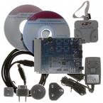
2. Kit Contents
The C8051F700 Development Kit contains the following items:
C8051F700 Target Board
C8051Fxxx Development Kit Quick-Start Guide
Silicon Laboratories IDE and Product Information CD-ROM. CD content includes:
Silicon Laboratories Integrated Development Environment (IDE)
Evaluation assembler, compiler and linker tools
Source code examples and register definition files
Documentation
AC to DC universal power adapter
USB debug adapter
2 USB cables
3. Hardware Setup
Refer to Figure 1 for a diagram of the hardware configuration.
1. Connect the USB Debug Adapter to the DEBUG connector on the target board with the 10-pin ribbon cable.
2. Connect one end of the USB cable to the USB connector on the USB Debug Adapter.
3. Verify that shorting blocks are installed on the target board as shown in Figure 1.
4. Connect the other end of the USB cable to a USB Port on the PC.
5. Connect the ac/dc power adapter to power jack P2 on the target board.
Notes:
Use the Reset icon in the IDE to reset the target when connected during a debug session.
Remove power from the target board and the USB Debug Adapter before connecting or disconnecting the
ribbon cable from the target board. Connecting or disconnecting the cable when the devices have power can
damage the device and/or the USB Debug Adapter.
Verzeichnis