
herunterladen
Semiconductor Components Industries, LLC, 2013
July, 2013 − Rev. 1
1 Publication Order Number:
AND8416/D
AND8416/D
Former Catalyst Document Number AN28
The CAT5132 Used for V
COM
Buffer Control in a TFT LCD
Display
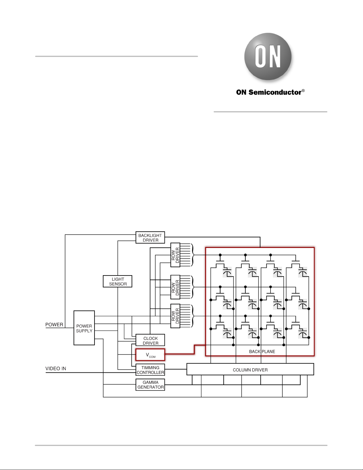
Application Overview
All TFT (Thin−Film−Transistor) LCD panels require at
least one appropriately tuned V
COM
signal to provide a
reference point for the panel’s back plane (or back plate).
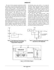
Figure 1 is a simplified block diagram to provide the
relationship of the V
COM
inputs within an LCD panel with
other inputs. The exact value of V
COM
varies from panel to
panel, so the manufacturer must program the voltage at the
factory to match the characteristics of each screen. An
appropriately tuned V
COM
value reduces flicker and other
undesirable effects.
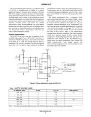
Solution History
Traditionally, the V
COM
adjustment made use of
mechanical potentiometers or trimmers (see Figure 2) in the
voltage-divider mode. In recent years, however, panel
makers have begun looking at alternative approaches
because inexpensive mechanical trimmers don’t provide the
manufacturing ease and desired reliability. The physical
adjustment process on the assembly line also leads to
inconsistent results from display to display. This adjustment
is not only time-consuming, but also prone to field failures
arising from human error and mechanical vibration.
Additionally low cost mechanical potentiometers tended to
be more vulnerable to environmental degradation over time
causing long term reliability issues.
Figure 1. Simplified Block Diagram of a TFT LCD Display
http://onsemi.com
APPLICATION NOTE
Verzeichnis