

herunterladen
SWRU284
March 2011
CC1101-CC1190EMK Quick Start Guide
Opening the box and using the modules with SmartRF04EB
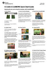
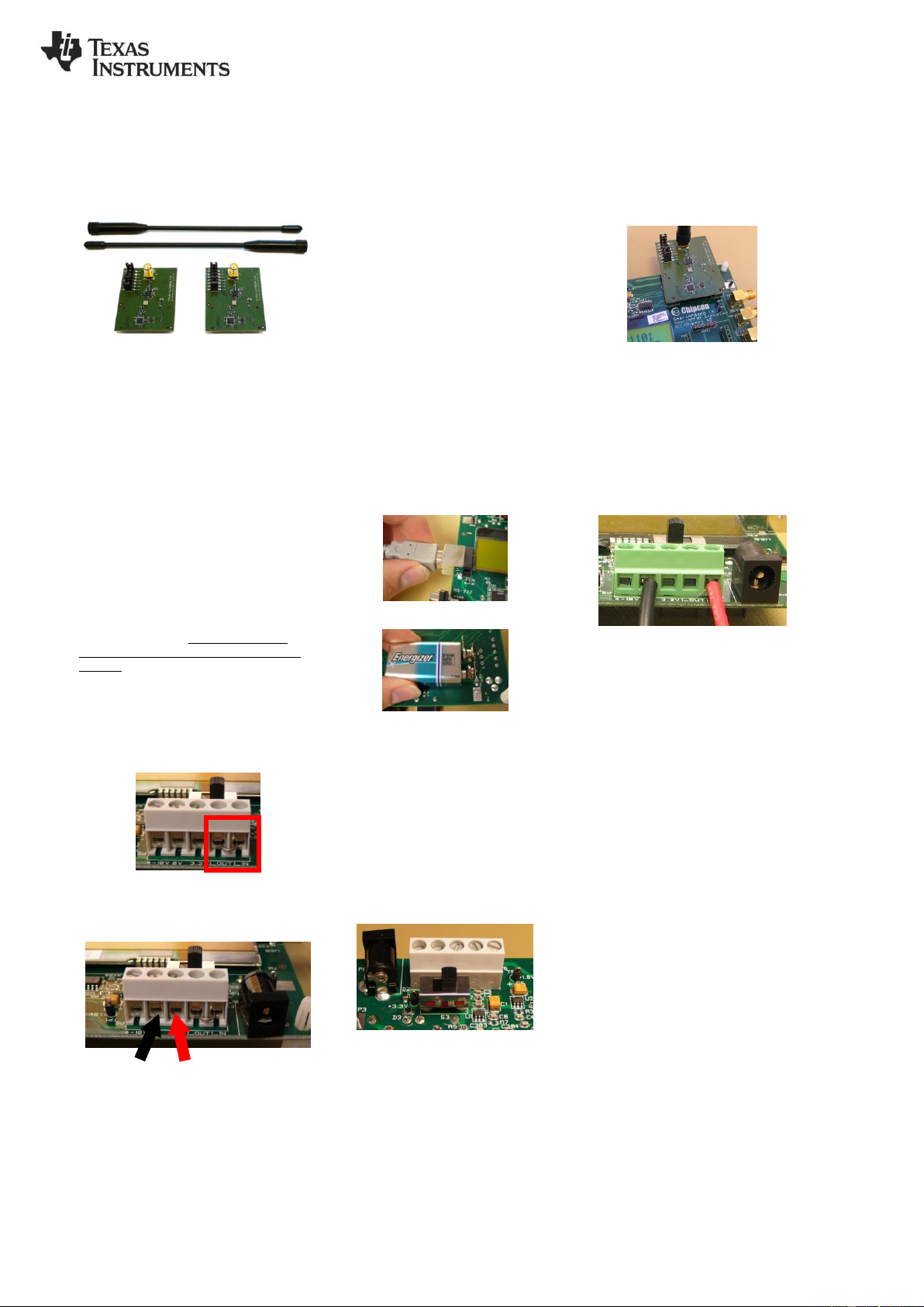
1. Kit Contents
2 x CC1101-CC1190EM
2 x Antennas
Documentation
The picture above shows the 869 MHz
version of the kit.
2. How to Use the Modules
The CC1101-CC1190 Evaluation Module
(EM) boards can be plugged into the
SmartRF04EB (EB), which is included in
the CC11xxDK. This board lets you control
the devices from SmartRF™ Studio and it
can also be used as a development
platform.
This Quick Start Guide describes how to
properly power an EB with a CC1101-
CC1190EM and how to control the combo
from SmartRF Studio.
3. Plug EM into SmartRF04EB
Insert the EM into the EB. The connectors
will only fit in one position, so that the EM
cannot be inserted the wrong way.
Handle the EM with care. Observe
precautions for handling electrostatic
sensitive devices.
4a. Apply Power
The EB can be powered from different
sources: USB, Battery or an External
Power Supply
The voltage regulator on the EB supplies
3.3 V to the assembly, but it can only
source up to 150 mA. It cannot supply the
CC1101-CC1190EM since it can consume
more than 300 mA. An external power
supply is therefore required for powering
the EM.
It is possible to have separate power
sources for the EB and for the EM. This is
controlled with the strap between I_OUT
and I_IN on P5 (the screw terminal).
Remove it to allow separate power
supplies.
4b. Power the EB
Connect the EB to a USB port on a PC.
Alternatively, connect a 9 V battery (not
included in the kit) to the battery connector
on the bottom side of the board.
Note that if multiple power sources are
connected, the source with the highest
voltage will power the EB. This means that
you should disconnect any attached
battery when using USB power; otherwise
the battery will be drained.
4c. Power the EM
As noted in 4a, remove the strap on P5
and connect the external power supply as
shown in the picture above. The red wire is
the positive supply and the black wire is
GND.
This will power the EM directly from the
external power supply, whereas the rest of
the EB will be powered from USB or the
battery.
The power supply range should be within
3.0 to 3.6 V.
4d. Optional: Same Power
Supply for both EB and EM
Connect a 3.3 V voltage source between
the 3.3 V and 0 V terminals. 3.3 V is the
middle terminal.
In this case, the on-board voltage regulator
will be bypassed. Note that the strap on P5
should not be removed.
5. Set Power Switch
If EB and EM are powered from different
sources as described in 4a-4c, the switch
should be set to the rightmost position.
If EB and EM are powered from the same
external supply as described in 4d, the
switch should be set to the leftmost
position.
This switch can be used to turn off the EB
by switching it to the opposite position of
that used to turn it on.
6. External Power Supply Range
With the test setup in 4a-4c, the EB is
connected to a 3.3 V supply through the
on-board voltage regulator and the EM is
powered by the external supply. Since the
EB is powered through a regulated 3.3 V
supply the signals going from CC1101-
CC1190 to the EB (and vice versa) need to
be within 3.0 V to 3.6 V. The external
supply connected to the EM when using
the setup in 4a-4c is therefore limited to 3.0
V to 3.6 V.
With the setup in 4d the supply range is
limited 2.7 V to 3.6 V.
GND
VDD