
herunterladen
Application Note 1815
May 2013
www.microsemi.com
1/32
DRF Series Design Guide
George J. Krausse
Microsemi Corp RF Power Products Group
405 SW Columbia St.
Bend, OR 97702 USA
gkrausse@microsemi.com
Dick Frey
Microsemi Corp RF Power Products Group
405 SW Columbia St.
Bend, OR 97702 USA
dfrey@microsemi.com
Introduction
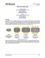
In this Design Guide we will detail the design process involved when using the DRF Series of devices and their
performance. As we move through this document it will be necessary to clearly define and explain multiple
technical points so that we have a mutual understanding of the key issues and how to address them. The DRF Series
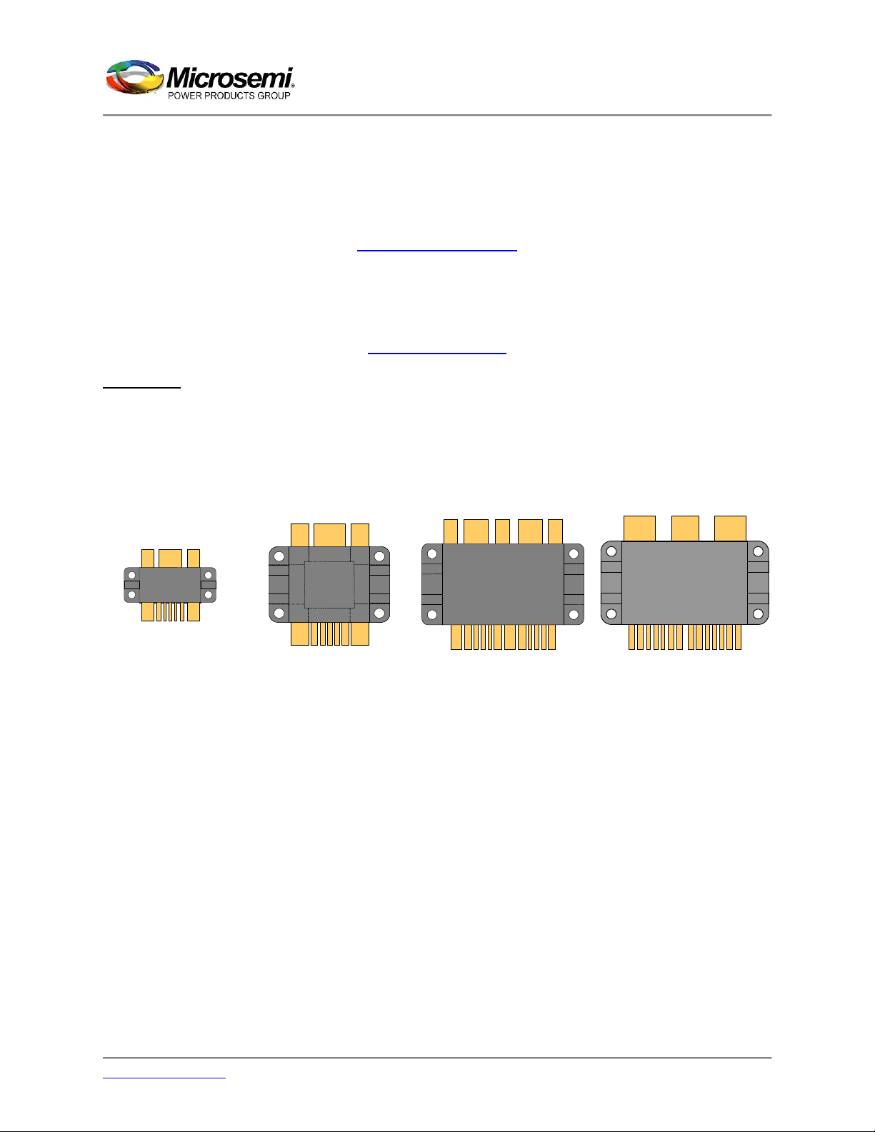
is based on a Flangeless Mechanical design illustrated in Figure 1. All of these devices incorporate at least one
driver die, the DRF100; all others have one or two driver die and one or two MOSFET devices.
1uF
1uF
1uF
1uF
1uF
1uF
DRF100
Microsemi
5600
5600
5600
5600
5600
5600
5600
5600
Microsemi
DRF1201
Microsemi
DRF1300
Microsemi
DRF1400
1
2 3 4 5
6 7 8
9 10 11
12 13 14
15
16
17
DRF100
Driver Test Device
and Die Qualification
package
DRF1200
Single Ended
Driver and 1 HV
MOSFET
DRF1300
Push-Pull
2 Driver and 2 HV
MOSFETs
DRF1400
Half-Bridge
2 Driver and 2 HV
MOSFETs
Figure 1. DRF Series Devices
The DRF100 was the platform used to develop and qualify the RF Driver IC. Understanding the design, layout and
function of the DRF100 is necessary to appropriately understand the DRF family of devices. The DRF devices are
capable of multiple Kilowatts at RF Frequencies of < 2MHz to > 30MHz; the DRF1200 Series 1KW; the DRF1300
Series 1-2KW; and the DRF1400 Series 2-3KW.
Verzeichnis