

herunterladen

User's Guide
SLAU643–July 2015
DRV10963 Evaluation Module
This document is provided with the DRV10963 customer evaluation module (EVM) as a supplement to the
DRV10963 datasheet (SLAS955A). It details the hardware implementation of the EVM and gives a step-
by-step introduction to the device operation and tuning process using DRV10963 GUI.
Contents
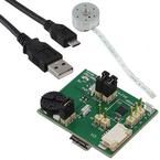
1 DRV10963 EVM Kit Contents.............................................................................................. 2
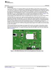
2 Introduction ................................................................................................................... 3
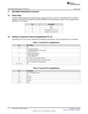
3 DRV10963 Motherboard Connectors ..................................................................................... 4
3.1 Power Input.......................................................................................................... 4
3.2 Interface Connectors to Mount Daughterboard P1, P2........................................................ 4
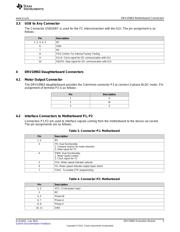
3.3 USB to Any Connector............................................................................................. 5
4 DRV10963 Daughterboard Connectors................................................................................... 5
4.1 Motor Output Connector ........................................................................................... 5
4.2 Interface Connectors to Motherboard P1, P2................................................................... 5
5 Quick Start Guide............................................................................................................ 6
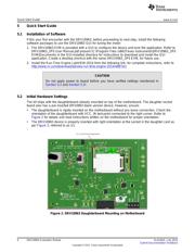
5.1 Installation of Software............................................................................................. 6
5.2 Initial Hardware Settings........................................................................................... 6
5.3 Jumpers and Switch Setup Settings ............................................................................. 7
5.4 Powering-Up EVM.................................................................................................. 7
5.5 Tuning GUI: to Configure Motor Parameter..................................................................... 8
6 Tuning Guide................................................................................................................ 13
6.1 Configuring the Device ........................................................................................... 13
6.2 Writing to the OTP Registers .................................................................................... 16
6.3 Reading the OTP Values......................................................................................... 18
6.4 Notes................................................................................................................ 18
7 Schematic and Bill of Materials........................................................................................... 20
7.1 Schematic .......................................................................................................... 20
7.2 Bill of Materials (BOM)............................................................................................ 22
List of Figures
1 DRV10963 Motherboard with Socket Daughterboard Mounted on top............................................... 3
2 DRV10963 Daughterboard Mounting on Motherboard ................................................................. 6
3 DRV10963 Orientation Inside Daughterboard Socket .................................................................. 7
4 GUI Initial Screen With Demo Mode ..................................................................................... 8
5 GUI Screen With Successful I2C Interface .............................................................................. 9
6 Default Configuration Parameters........................................................................................ 10
7 Loading DRV10963JM Configuration Parameter to Device .......................................................... 11
8 DRV10963JM Configuration Parameter ................................................................................ 12
9 Initial Tuning Flow Chart................................................................................................... 12
10 Error Message.............................................................................................................. 13
11 Correct Align Time and Acceleration Rate.............................................................................. 14
12 Align Time Too Long....................................................................................................... 14
13 Align Time Too Short ...................................................................................................... 14
14 Open to Close Loop Threshold Too Low................................................................................ 14
1
SLAU643–July 2015 DRV10963 Evaluation Module
Submit Documentation Feedback
Copyright © 2015, Texas Instruments Incorporated
Verzeichnis