
herunterladen

Maxim > Design Support > Technical Documents > Reference Schematics > 1-Wire
®
Devices > APP 4477
Maxim > Design Support > Technical Documents > Reference Schematics > iButton
®
> APP 4477
Keywords: 1-Wire, iButton, voltage level translation, 1.8V to 5V, MAX3394E, FPGA, 1-Wire master
REFERENCE SCHEMATIC 4477
Reference Design of a 1-Wire® Bidirectional Voltage-
Level Translator for 1.8V to 5V
By: Stewart Merkel, Senior Member Technical Staff
Nov 11, 2009
Abstract:
Designers need open
-drain logic to run at 1.8V at the 1-Wire master IO. Most 1-Wire slave devices
cannot run at 1.8V. This application note presents an RD (reference design) of a circuit that translates from a
1.8V 1-Wire master to a 5V 1-Wire slave device. The RD is used for driving typical 1-Wire slave devices. The
MAX3394E voltage-level translator is featured in the design.
Introduction
Devices such as FPGAs, microprocessors, the DS2482-100, and DS2480B are examples of 1-Wire master
devices. The 1-Wire/i
Button® slave devices are manufactured by Maxim and comprise an extensive family of
parts that typically operate from 2.8V to 5.25V. The 1-Wire masters and slave devices have traditionally been
5V open-drain logic in the past.
Today designers need open-drain logic to run at 1.8V at the 1-Wire master IO. While most 1-Wire slave
devices can run safely at 5V, most of those same devices cannot run at 1.8V. A bidirectional voltage-level
translator circuit is needed to overcome this limitation. This RD (reference design) features the Maxim®
MAX3394E, which is a bidirectional voltage-level translator for these applications.
Voltage-Level Translator
The MAX3394E is a dual-level translator available in an 8-pin, 3mm x 3mm TDFN package. It is ideal for
driving high-capacitive loads, thanks to its internal slew-rate enhancement circuitry. 1-Wire slave devices often
have capacitive loading greater than 500pF. The MAX3394E's V
CC
I/O pins are protected to ±15kV HBM
(Human Body Model), which protects the 1-Wire master. The 1-Wire bus architectures often interface to the
external world, making HBM essential. However, it is recommended that a DS9503P be added as ESD
protection for the pullup resistor (R3), the optional strong pullup circuitry, and the 1-Wire slave device.
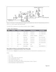
Application Circuit
The circuit in Figure 1 shows the MAX3394E used to perform bidirectional 1.8V to 5V voltage-level translation
in an open-drain system.
Page 1 of 6