


herunterladen

1
Application Note 1532
ISL28006 Evaluation Board User’s Guide
Introduction
The ISL28006 evaluation board is a design platform
containing all the circuitry needed to characterize critical
performance parameters of the ISL28006 in either a high
side or low-side current sense application. The ISL28006
is available in fixed 100V/V, 50V/V, 20V/V and adjustable
gains.
Reference Documents
• ISL28006 Data Sheet, FN6548
Evaluation Board Schematic
The ISL2800XEVAL1Z evaluation board is configured
with either the ISL28006-100, ISL28006-50,
ISL28006-20 or the ISL28006-ADJ device (adjustable
gain via external resistors R
11
and R
14
). Note: When
using the adjustable part, V-REF (J
1
) needs to be
grounded. J
13
is provided to enable accurate voltage
measurements across the sense resistor R
3
.
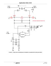
Figure 1 shows the basic application circuit and optional
protection components for the fixed gain parts. Figure 2
shows the basic application circuit and optional
protection components for the adjustable gain part.
Figure 3 shows the complete schematic for the
ISL2800XEVAL1Z evaluation board.
Components shown in red in both Figures 1 and 2 are
optional transient protection and not required for clean
environments. Note: The evaluation board comes
equipped with the transient protection devices.
Optional Transient Protection
For applications where the load and the power source are
permanently connected, transient protection is not
required and only an external current sense resistor (R
3
)
is needed.
For applications where fast transients can generate
voltage spikes that can overdrive the amplifier input and
drive the output of the amplifier into the rails, a long
overload recovery time will result. Common mode
capacitors C
7
, C
9
and differential capacitor C
8
are used
to filter the common mode and differential voltage
spikes.
For switching applications or where fast transients are
caused by hot plugging the source or load, external
protection components may be needed. The external
current limiting resistor (R
6
) in Figure 1 will limit the
peak current through the internal ESD diodes to <20mA.
This condition can occur in applications that experience
high levels of in-rush current causing high peak voltages
that can damage the internal ESD diodes of the
ISL28006. If the current limiting resistor is required, it
needs to be placed on the RS- input (R
6
). Placing it on
the RS+ input side (R
7
) will result in a much larger error
voltage due to the ISL28006 taking its supply current
from the sense current in high-side applications.
For example:
Current limiting resistor R
6
with a value of 100Ω will
provide protection for a 2V transient with the maximum
of 20mA flowing through the input while adding only an
additional 13µV (worst case over-temperature) of V
OS
as
shown in Equation 1. Note: Worst case over-temperature
input bias current on the RS- input is 130nA.
Current limiting resistor R
7
with value of 100Ω will
provide the same transient protection, but with an error
voltage of 800µV. Note: Worst case over-temperature
input bias current on the RS+ input is 8µA as shown in
Equation 2.
R
7
is a carry-over from our characterization board and
was used to measure input bias current. The evaluation
board is populated with a zero ohm resistor for R
7
.
Power Supplies
External power connections are made through the VS+
and Ground connections on the evaluation board.
Capacitors C2 and C4 perform two duties, de-coupling
the supplies and filtering of the power supply noise with
R
15
. Anti-reverse diodes D
1
and D
3
protect the circuit in
the case of accidental polarity reversal of the supply.
Resistor R
12
is used to connect ground to the fixed gain
parts.
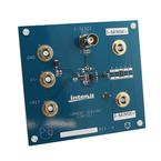
ISL2800XEVAL1Z and BOM
Figure 4 shows the top view of the ISL2800XEVAL1Z
evaluation board. The evaluation board Bill of Materials
is given in Table 2.
R
6
I
RS-
× 100Ω 130nA× 13μV==
(EQ. 1)
R
7
I
RS+
× 100Ω 8μA× 800μV==
(EQ. 2)
CAUTION: These devices are sensitive to electrostatic discharge; follow proper IC Handling Procedures.
1-888-INTERSIL or 1-888-468-3774
| Intersil (and design) is a registered trademark of Intersil Americas Inc.
Copyright Intersil Americas Inc. 2010. All Rights Reserved
All other trademarks mentioned are the property of their respective owners.
April 12, 2010
AN1532.1