
herunterladen
1
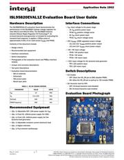
ISL95820EVAL1Z Evaluation Board User Guide
Hardware Description
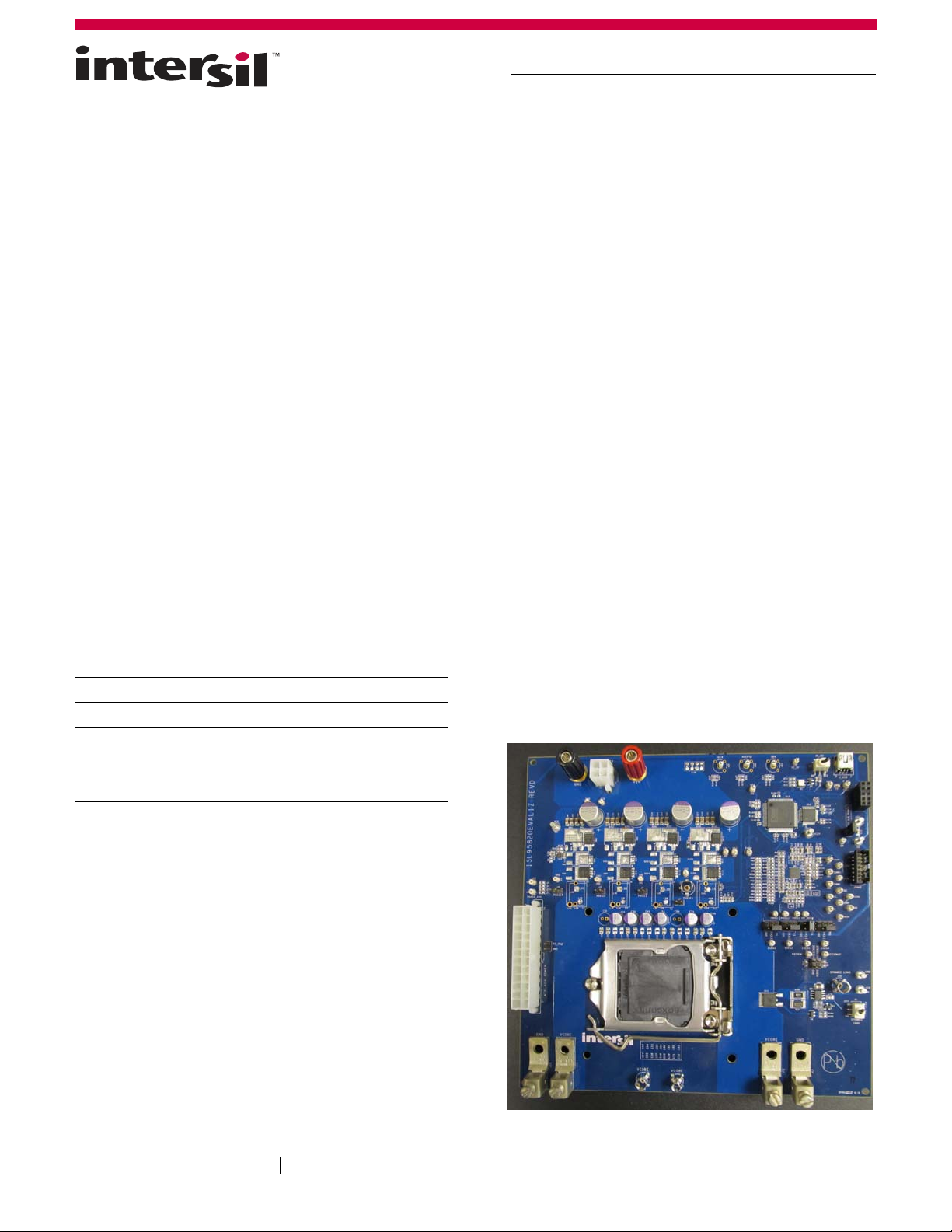
The ISL95820EVAL1Z evaluation board demonstrates the
performance of the ISL95820 4-phase voltage regulator for
Intel VR12.5 and VR12.6 CPUs. The ISL95820 features
Intersil's Robust Ripple Regulator R3 Technology™. An
on-board dynamic-load generator is included for evaluating the
transient-load response. It applies a 300µs pulse of
approximately 0.05/0.1load across V
CORE
and PGND.
Contents of this document include:
• Design criteria
• Recommended test equipment
• Interface connections
• Switch descriptions
• Photographs of the evaluation board and PMBus interface
module.
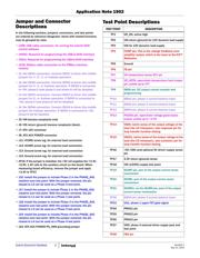
• Jumper and connector descriptions
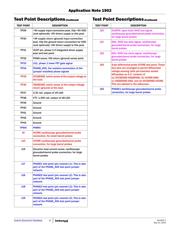
• Test point descriptions
• Evaluation board documentation
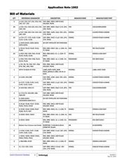
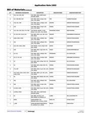
- Bill of materials
-Schematic
- Silk-screen plots
- Board layer plots
Recommended Equipment
• (Qty. 1) Adjustable 20V, 15A power supply (for V
IN
)
• (Qty. 1) Fixed 5V, 100mA power supply (for VDD)
• (Qty. 1) Fixed 12V, 100mA power supply (for the
dynamic-load generator)
• (Qty. 1) Adjustable constant current electronic load
•(Qty. 1) Digital voltmeter
• (Qty. 1) Four-channel oscilloscope
Interface Connections
•V
IN
: Input voltage to the power stage
-J5: V
IN
positive power input
-TP18: V
IN
positive voltage sense
-J6: V
IN
return power input
- TP32: V
IN
return voltage sense
•CPU V
CORE
: CORE regulated output voltage
-J11 and J12: V
CORE
positive power output
- J13 and J14: V
CORE
return power output
• +5V: +5V input voltage
- TP29: +5V positive input
- TP16: +5V sense
- TP30: +5V return input
• +12V: Input voltage for the dynamic-load generator
- TP3: 12V positive input
-TP2: 12V return input
Switch Descriptions
•S3: Enable
- OFF: Short the VR_ON pin to GND (disable PWM)
- ON: Allow the VR_ON pin to pull-up to +5V (enable PWM)
• S2: Dynamic load for CPU
- OFF: On-board dynamic load disabled
-ON: On-board dynamic load enabled
Evaluation Board Photograph
TABLE 1. DC/DC DESIGN CRITERIA
PARAMETER VALUE UNITS
V
IN
12 VDC
V
O
0 to 2.30 VDC
Full-load 100 ADC
PWM Frequency 300 kHz
CAUTION: These devices are sensitive to electrostatic discharge; follow proper IC Handling Procedures.
1-888-INTERSIL or 1-888-468-3774
| Copyright Intersil Americas LLC 2013, 2014. All Rights Reserved
Intersil (and design) and R3 Technology are trademarks owned by Intersil Corporation or one of its subsidiaries.
All other trademarks mentioned are the property of their respective owners.
May 21, 2014
AN1902.1
Application Note 1902