
herunterladen
1
®
ISL62383 Triple-Output Evaluation
Board User Guide
Introduction
The ISL62383 evaluation board demonstrates the
performance of ISL62383 triple-output controller. The
ISL62383 controller includes two pulse-width modulation
(PWM) controllers featured with Intersil’s patented R
3
technology, adjustable from 0.6V to 5.5V, and one linear
regulator LDO5, which generates a fixed 5V output and can
deliver up to 100mA.
The evaluation board includes two independent Enable
switches, two LED Power-Good indicators and various test
points. Included with each switching channel is an on-board
dynamic load generator for evaluating the transient-load
response. There are two different evaluation boards which
provide flexible evaluation options. Table 1 shows a brief
description of the evaluation boards.
What’s Inside
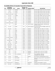
The Evaluation Board Kit contains the following materials:
• ISL62383xxEVAL1Z Evaluation Board
• ISL62383 Datasheet
• ISL62383 Evaluation Board User Guide (this document)
What’s Needed
The following materials will be needed in order to perform
testing:
• Adjustable +25V, 30A Power Supply
• +12V, 100mA Power Supply
• Precision Digital Multimeter
• 3 Electronic Loads
• 4-Channel Oscilloscope
Enable Control
The evaluation board provides flexible control logic to enable
or disable the outputs, and to program the two PWM
channels’ start-up sequence. For start-up timing sequence,
please refer to the ISL62383 datasheet waveforms. Table 2
is the Enable controller truth table.
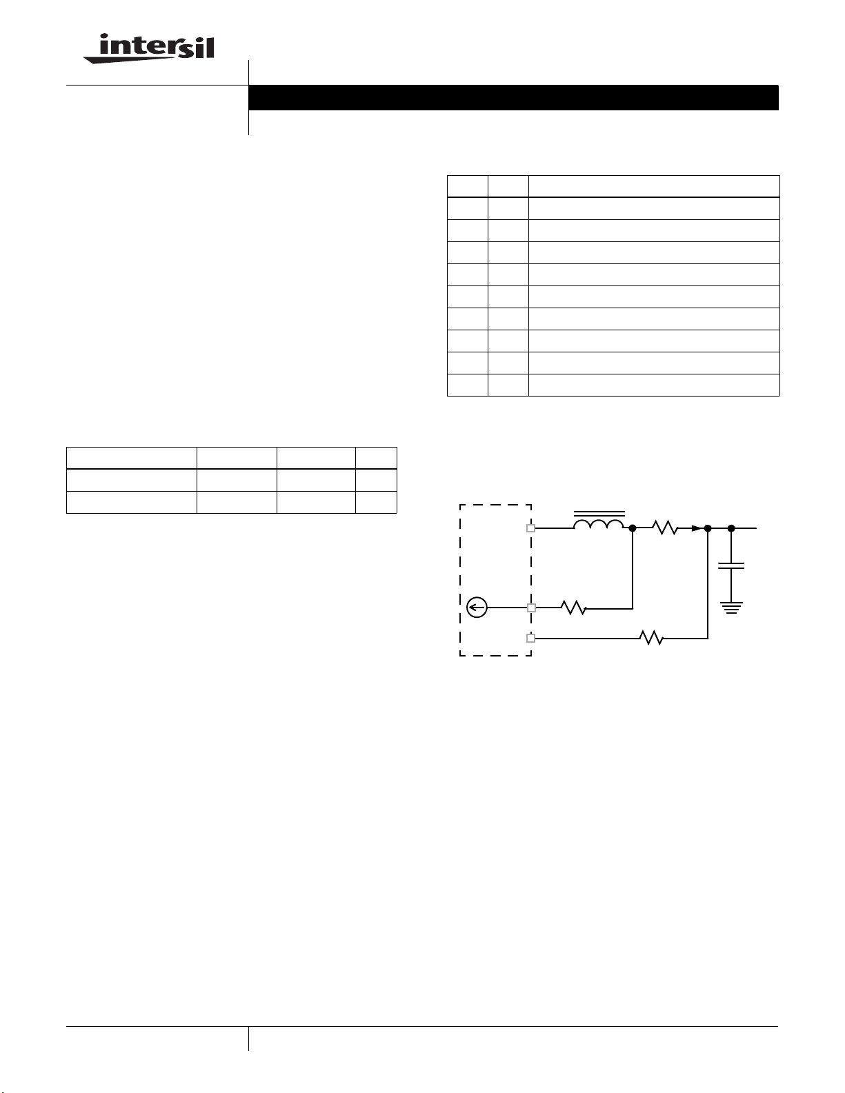
Resistor Current Sense Configuration
The Evaluation Board is pre-configured with inductor DCR
current sense. For more precise overcurrent protection, it
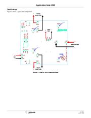
also provides the option of resistor current sense. Figure 1
shows the configuration for resistor current sense.
For Channel-1, the ISL62383 monitors the OCSET1 pin and
the ISEN1 pin voltages. Once the OCSET1 pin voltage is
higher than the ISEN1 pin voltage for more than 10µs, the
ISL62383 declares an overcurrent fault. For a chosen
overcurrent set point I
OC
and current sense resistor R
SENSE
,
the value of R
OCSET
is determined by Equation 1:
Where:
-R
OCSET
(Ω) is the resistor used to program the
overcurrent setpoint
-I
OC
is the output current threshold that will activate the
OCP circuit
-R
SENSE
is current sense resistor (R
3
for Channel-1;
R
25
for Channel-2)
TABLE 1. EVALUATION BOARDS DESCRIPTION
EVALUATION BOARD CHANNEL-1 CHANNEL-2 OCP
ISL62383LOEVAL1Z 3.3V/8A 5V/8A ~10A
ISL62383HIEVAL1Z 1.05V/15A 1.5V/15A ~20A
TABLE 2. ENABLE TRUTH TABLE
EN1 EN2 START-UP SEQUENCE
Low Low Both Channels outputs OFF simultaneously
Low Float Both Channels outputs OFF simultaneously
Float Low Both Channels outputs OFF simultaneously
Float Float Both Channels outputs OFF simultaneously
Low High Channel-1 OFF, Channel-2 ON
High Low Channel-1 ON, Channel-2 OFF
High High Both Channels outputs ON simultaneously
Float High Channel-1 enabled after Channel-2 is in regulation
High Float Channel-2 enabled after Channel-1 is in regulation
FIGURE 1. RESISTOR CURRENT SENSE CIRCUIT
PHASEx
C
O
L
V
O
OCSETx
ISENx
R
O
ISL62383
I
L
10µA
+
_
V
RSENSE
+
V
ROCSET
_
R
SENSE
R
OCSET
(EQ. 1)
R
OCSET
I
OC
R
SENSE
•
10μA
-------------------------------------
=
July 31, 2008 AN1398.0Application Note
CAUTION: These devices are sensitive to electrostatic discharge; follow proper IC Handling Procedures.
1-888-INTERSIL or 1-888-468-3774
| Intersil (and design) is a registered trademark of Intersil Americas Inc.
Copyright Intersil Americas Inc. 2008. All Rights Reserved
All other trademarks mentioned are the property of their respective owners.