
herunterladen
1
®
AN1461.1
CAUTION: These devices are sensitive to electrostatic discharge; follow proper IC Handling Procedures.
1-888-INTERSIL or 1-888-468-3774
| Intersil (and design) is a registered trademark of Intersil Americas Inc.
Copyright Intersil Americas Inc. 2009. All Rights Reserved
All other trademarks mentioned are the property of their respective owners.
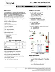
ISL62882EVAL2Z User Guide
Introduction
The ISL62882EVAL2Z evaluation board demonstrates the
performance of the ISL62882 multiphase synchronous-buck
PWM V
CORE
controller implementing Intel IMVP-6.5
protocol. The ISL62882 features Intersil's Robust Ripple
Regulator (R
3
) technology. An on-board dynamic-load
generator is included for evaluating the transient-load
response. It applies a 300µs pulse of approximately 25mΩ
load across V
O
and PGND.
Contents of this document include:
• Design Criteria
• Recommended Test Equipment
• Interface Connections
• Switch Descriptions
• DIP Switch Descriptions
• Jumper Descriptions
• Test Point Descriptions
• Evaluation Board Documentation
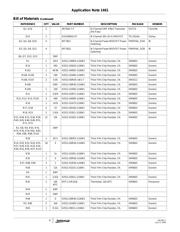
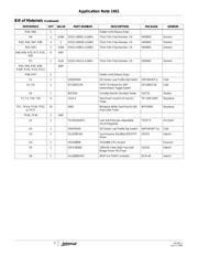
- Bill of materials
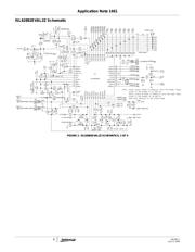
- Schematic
- Silk-screen plots
- Board layer plots
Recommended Equipment
• (QTY 1) Adjustable 25V, 10A Power Supply
• (QTY 1) Fixed 5V, 100mA Power Supply
• (QTY 1) Fixed 12V, 100mA Power Supply
• (QTY 1) Adjustable Constant Current Electronic Load
• (QTY 1) Digital Voltmeter
• (QTY 1) Four-Channel Oscilloscope
Interface Connections
•V
IN
: Input Voltage to the Power Stage
-J5: V
IN
Positive Power Input
-TP31: V
IN
Positive Voltage Sense
-J6: V
IN
Return Power Input
-TP32: V
IN
Return Voltage Sense
•V
O:
Regulated Output Voltage
- J11 and J12: V
O
Positive Power Output
- J13 and J14: V
O
Return Power Output
• +5V: +5V Input Voltage
- TP29: +5V Positive Input
- TP30: +5V Return Input
• +12V: Input Voltage for the Dynamic-load Generator
- TP3: 12V Positive Input
- TP2: 12V Return Input
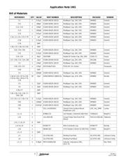
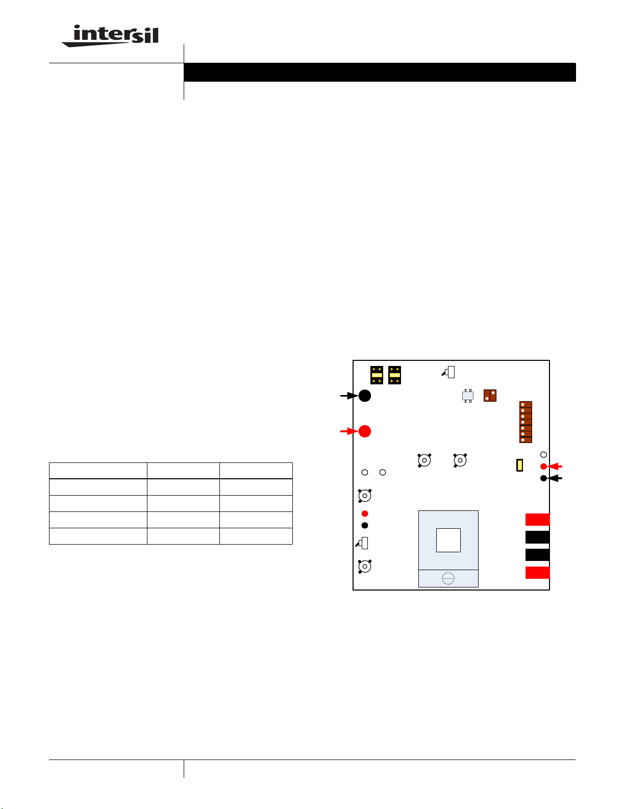
Test Set-up
FIGURE 1. TEST SET-UP
Switch Descriptions
• S3: Enable
- OFF: Short the VR_ON pin to GND (disable PWM)
- ON: Allow the VR_ON pin to pull-up to +5V (enable
PWM)
• S5: Dynamic Load
- OFF: On-board dynamic load disabled
- ON: On-board dynamic load enabled
TABLE 1. DC/DC DESIGN CRITERIA
PARAMETER VALUE UNITS
V
IN
4.5 to 20 VDC
V
O
0 to 1.5 VDC
Full-load 60 ADC
PWM Frequency 300 kHz
10
U2
ISL62882 EVAL2Z
ON
OFF
0
1
TP37
TP29
TP30
J8J7
VID0
VID1
VID2
VID3
VID4
VID5
VID6
VIN
+
_
TP35 TP36
PHASE1 PHASE2VSSSENSEVCCSENSE
J10
VCORE
ON
OFF
S3
S2
TP3
TP2
5V
+
_
J12
VCORE
J11
VCORE
J14
PGND
J13
PGND
J1J2
S1
PSI#
DPRSLPVR
+3.3V
+5V
PGND
J6
PGND
J5
VIN
D1
J16
Application Note July 13, 2009
Author: Jia Wei