

herunterladen
1
®
AN9993
CAUTION: These devices are sensitive to electrostatic discharge; follow proper IC Handling Procedures.
1-888-INTERSIL or 1-888-468-3774
| Intersil (and design) is a registered trademark of Intersil Americas Inc.
Copyright © Intersil Americas Inc. 2002. All Rights Reserved
V
DDQ
and V
TT
Termination Regulation for DDR
DRAM Memory Power Utilizing the ISL6530
Introduction
The ISL6530 and the ISL6531 are dual, voltage mode
controllers with many functions that are needed for DDR
DRAM Memory power applications. The ISL6530 and
ISL6531 contain high performance error amplifiers, a high
accuracy reference, an internal 50% tracking reference, a
fixed 300kHz internal oscillator with a 90
o
phase shift for
dual synchronous buck regulators, over-current protection
circuitry, Power Good indication, and two shut down options.
There are two MOSFET drivers for use in both synchronous-
rectified Buck converters. The ISL6530 and ISL6531 are
also capable of regulating the output voltage while the
tracking DC-DC converter is sinking current. All these
features are packaged in a 24 lead SOIC or a small 32 Lead
4x4[mm] MLFP.
ISL6530 and ISL6531
The ISL6530 and ISL6531 are pin for compatible
replacements to each other. All functions are identical
between the two ICs. The difference between the ISL6530
and the ISL6531 lies in the compensation of the V
TT
regulator. The ISL6531 features internal compensation for
the V
TT
regulator. More complete descriptions of both ICs
can be found in their respective datasheets[1,2].
Reference Designs
There are four different evaluation boards that are included
in the scope of this application note. Table 1 describes each
of the boards.
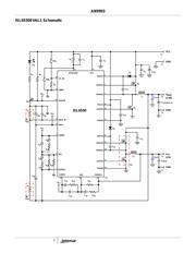
The ISL6530EVAL1 is an evaluation board that highlights
the operation of the ISL6530 in an embedded DDR DRAM
Memory Power application. The V
DDQ
supply has been
designed to supply 2.5V at a maximum load of 10A. The V
TT
termination supply will track the V
DDQ
supply at 50% and
was designed for a maximum load of 5A, sourcing or sinking.
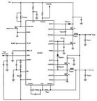
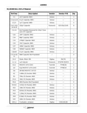
The schematic, Bill of Materials, and Board Layout for the
ISL6530EVAL1 can be found in the Appendix. Customization
of the reference design is discussed in this application note.
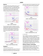
Quick Start Evaluation
The ISL6530/31EVAL1 board is shipped ‘ready to use’ right
from the box. The ISL6530/31EVAL1 board will only accept
5V from a standard power supply. Both outputs can be
exercised through external loads. The V
TT
regulator has the
ability to source or sink current while the V
DDQ
regulator
may only source current.
There are posts available on the board for introducing power
to the board and also for drawing current from the regulated
outputs. Two probe points are also available for use. These
probe points provide Kelvin connections to the PGOOD
(TP4) and VREF_OUT (TP3) pins.
An LED lights up to indicate that the output voltages are
within regulation.
Recommended Test Equipment
To test the functionality of the ISL6530, the following
equipment is recommended:
- A 5V, 10A capable bench power supply
- Two electronic loads
- Four channel oscilloscope with probes
- Precision digital multimeters
Power and Load Connections
There are 3 sets of jumpers that are used for the supplying
the input voltage and loading the V
DDQ
and V
TT
outputs.
INPUT VOLTAGE
Connect the positive lead of the 5V bench power supply
to the VCC post (J1). Connect the ground lead of the
supply to GND post (J2).
LOADING V
DDQ
Connect the positive terminal of the first electronic load to
the VDDQ post (J3). Connect the return terminal of the
same load to the GND post (J4).
LOADING V
TT
- SOURCING CURRENT
To test V
TT
while the regulator sources current, connect
the positive terminal of the second electronic load to the
VTT post (J5). Connect the return terminal of the same
load to the GND post (J6).
LOADING V
TT
- SINKING CURRENT
To test V
TT
while the regulator sinks current, connect the
positive terminal of the second electronic load to the
VDDQ post (J3). Connect the return terminal of the same
load to the VTT post (J5).
CAUTION: The return terminal of the load must float for
this to work properly.
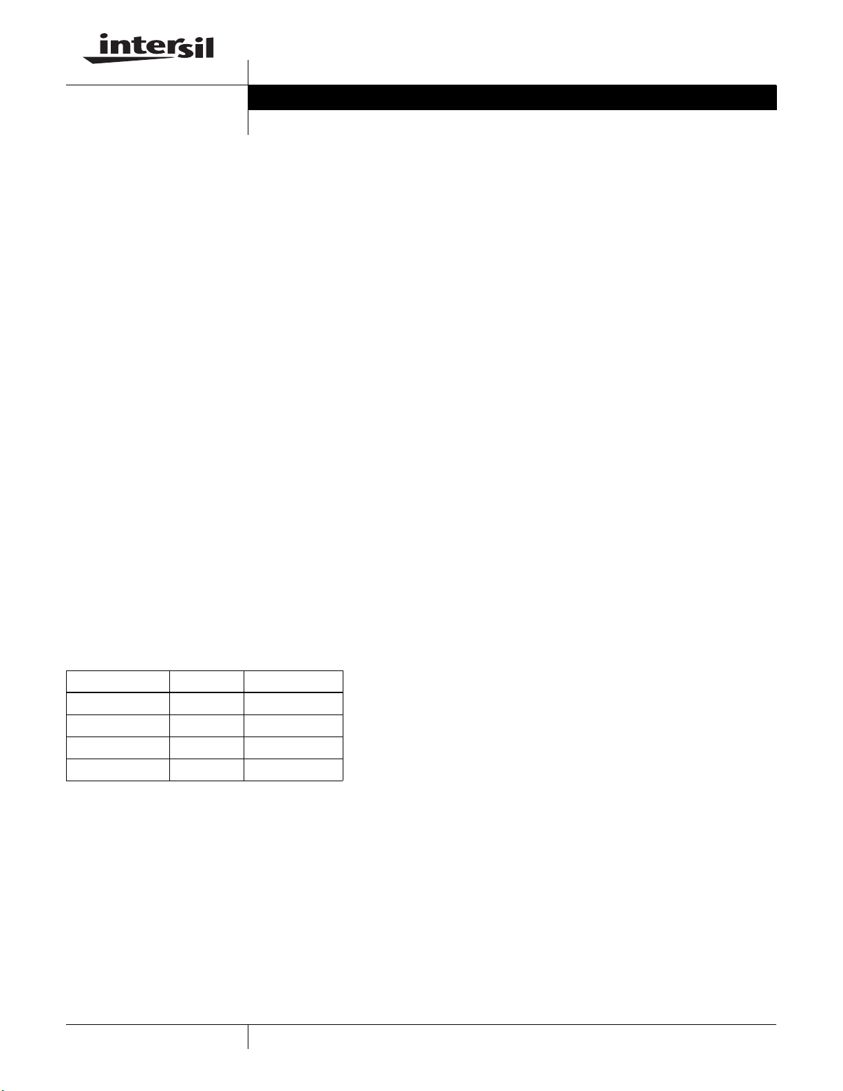
Table 1 - Evaluation Boards
Board Name IC Package
ISL6530EVAL1 ISL6530CB 24 ld SOIC
ISL6530EVAL2 ISL6530CR 32 ld 4x4 MLFP
ISL6531EVAL1 ISL6531CB 24 ld SOIC
ISL6531EVAL2 ISL6531CR 32 ld 4x4 MLFP
April 2002
Author: Douglas Mattingly
Application Note