

herunterladen
1
CAUTION: These devices are sensitive to electrostatic discharge; follow proper IC Handling Procedures.
1-888-INTERSIL or 1-888-468-3774
| Intersil (and design) is a registered trademark of Intersil Americas Inc.
Copyright Intersil Americas Inc. 2009. All Rights Reserved
All other trademarks mentioned are the property of their respective owners.
Application Note 1491
ISL6721EVAL3Z: Resonant Reset Forward
Converters for Low Power Applications
Abstract
Low cost, isolated power supplies with multiple outputs
are common in many applications such as automotive,
security monitoring, telecom, medical instruments, etc.
For these applications, multiple output rails are needed
for integrated circuits (IC) with different operation
voltages on the same printed circuit board (PCB). Usually
the voltage regulation of these outputs are not tight, and
the current level not high. Isolation between the
converter’s input and output is necessary for safety
considerations and ground separation. Isolated power
converters with multiple secondary side windings provide
low cost solutions for these applications. Intersil’s
isolated power family products support these applications
with both double-ended PWM controllers (ISL6740,
ISL67401, ISL6742, ISL6743, ISL6745), and single-
ended PWM controllers (ISL6840, ISL6841, ISL6842,
ISL6843, ISL6844, ISL6845, ISL6721, ISL6722, and
ISL6723). Single-ended flyback and forward converters
based on ISL6721 are the most frequently used because
of its high performance and low cost.
The ISL6721EVAL3Z board serves as a reference design
for single switch resonant reset forward converter with
multiple outputs for typical industry applications that
need isolation. It can be used for security monitoring
systems where an input voltage range of 21.6V to 52.8V
is typical for operation from a battery source of 24V or
48V with 10% tolerance.
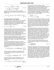
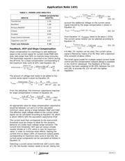
Design Specifications
The evaluation board ISL6721EVAL3Z aims at the
following design specifications.
• Switching Frequency, . . . . . . . . . . . Fsw: 300kHz
• Input Voltage Range, V
IN
: 21.6V DC to52.8V DC
• Output Voltage 1, V
OUT1
: 12V with 5% Absolute
Regulation
• Output Current 1, I
OUT1
: 2.5A
• Output Voltage 2, V
OUT2
: 18V with 5% Absolute
Regulation
• Output Current 2, I
OUT2
: 1A
• Overall Output Power, P
OUT
: 48W
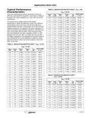
• Full Load Efficiency: 80% under all Line and Load
Conditions
• Output Voltage Ripple: 50mV
P-P
on each Rail
• Minimum Load: 25% on 12V Rail, 20% on 18V
Output.
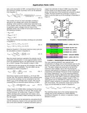
Description of Circuit Operation
The ISL6721 is a high performance single-ended PWM
controller intended for various isolated and non-isolated
applications for telecom power supply, server power and
industrial power supply. It can be used in various single
transistor topologies including forward and flyback
regulators, boost converters, buck-boost converters, and
SEPIC converters. With the rich protection and control
features, it provides optimal solutions for single ended
current mode PWM controlled isolated power converters
with minimum external components and high
performance.
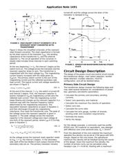
A single switch forward topology has higher efficiency
over the cheap flyback converters, and is widely
accepted for less than 100W applications. However, the
forward transformer needs to be reset within each
switching cycle. There are mainly three reset methods,
that is, reset winding plus diode, active clamp switch,
and resonant reset with capacitor. In a resonant reset
converter (RRF), a reset capacitor is connected to the
drain source of the transistor. As the main switch is
turned off, a resonance is developed between the
magnetizing/leakage inductance and the equivalent
resonant capacitor. The high voltage across the drain of
the switch resets the core of the transformer. Only one
switch is used, and it does not need a reset winding or
diode.
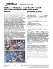
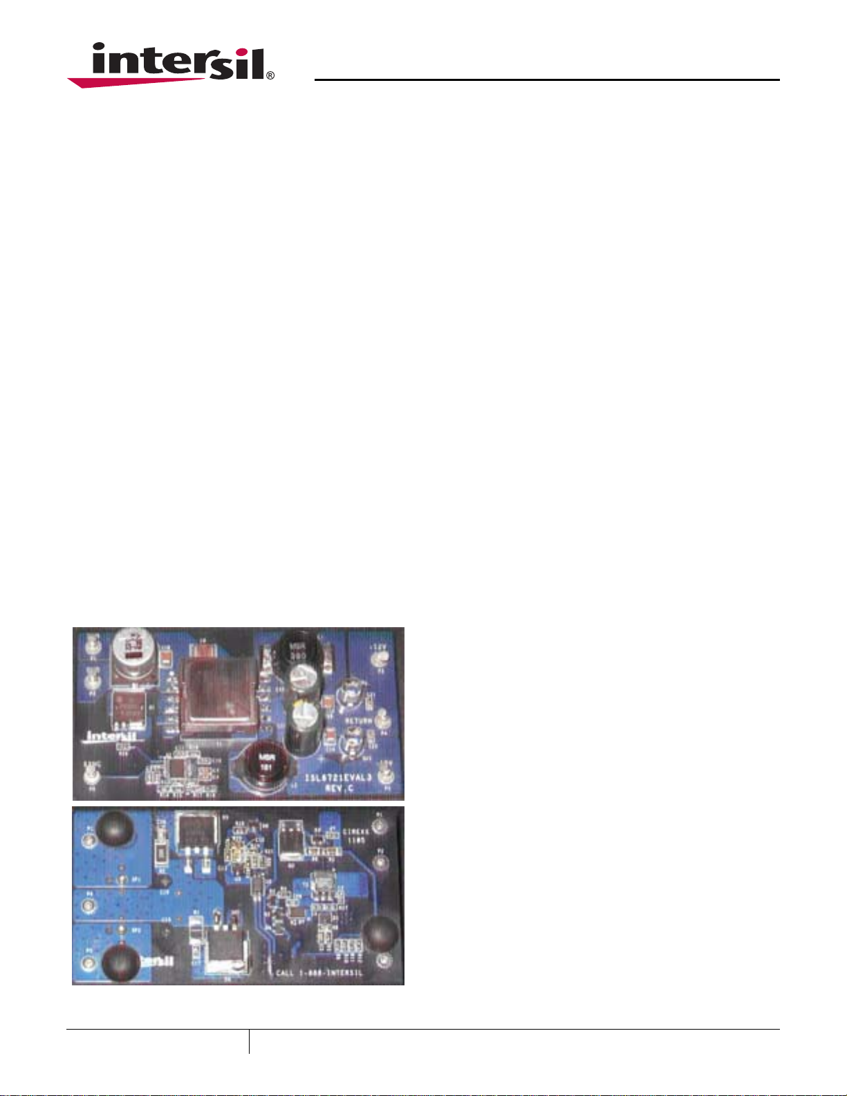
FIGURE 1. TOP AND BOTTOM VIEW OF THE PCB BOARD
September 2, 2009
AN1491.0
Verzeichnis
- ・ Blockdiagramm on Seite 2 Seite 3 Seite 8
- ・ Technische Daten on Seite 1
- ・ Anwendungsbereich on Seite 1
- ・ Elektrische Spezifikation on Seite 6