
herunterladen
1
ISL9305/ISL9305H Evaluation Board User Guide
Evaluation Board Features
• Input voltage rating from 2.3V to 5.5V for ISL9305 and 2.5V
to 5.5V for ISL9305H
• Two 800mA buck converters for ISL9305 and two 1.5A buck
converters for ISL9305H
• Two 300mA LDOs
• Output voltages are programmable with I
2
C
• 3MHz switching frequency
• Connector, test point and Jumper
Required Equipment
• Power supply capable of delivering up to 5.5V and 3A
• Electronic load
• Voltmeter, Oscilloscope
Quick Setup Guide
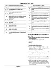
1. Install jumpers on JP3, JP4, JP8 and JP9.
2. Connect power supply to VCC, with voltage setting within
voltage rating.
3. Connect electronic loads at VODCD1, VODCD2, with load
setting up to 800mA for ISL9305, and 1.5A for ISL9305H.
4. Connect electronic loads at VOLDO1, VOLDO2, with current
setting up to 300mA.
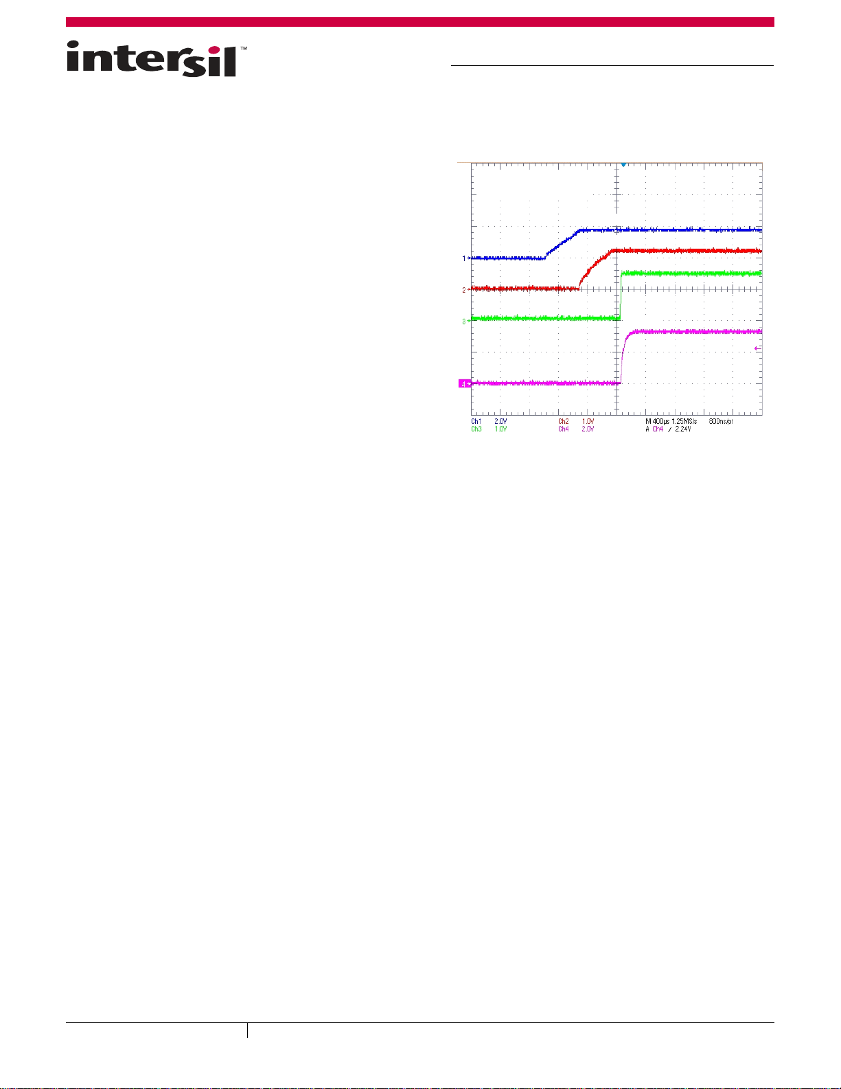
5. Place scope probes at 4 outputs.
6. Turn on the power supply.
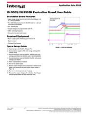
7. Monitor output voltages start-up sequence in default on the
scope. The waveforms will look similar to that shown in
Figure 1.
8. Turn on the electronic loads at all outputs.
9. Measure the output voltages with voltmeter. The voltages
should regulate within the data sheet spec limit.
VODCD1
VODCD2
LDO1
LDO2
DEFAULT START-UP
NO LOAD
FIGURE 1. START-UP SEQUENCE
June 4, 2012
AN1564.1
CAUTION: These devices are sensitive to electrostatic discharge; follow proper IC Handling Procedures.
Copyright Intersil Americas Inc. 2010, 2012. All Rights Reserved.
1-888-INTERSIL or 1-888-468-3774
| Intersil (and design) is a trademark owned by Intersil Corporation or one of its subsidiaries.
All other trademarks mentioned are the property of their respective owners.
Application Note 1564