herunterladen

User's Guide
SLOU262 – July 2009
Isolated CAN Transceiver EVM
This User Guide details the design and operation of the evaluation module (EVM) for the ISO1050 isolated
CAN transceiver.
This Guide explains the user configurable I/O loads for the EVM configurations, and presents a typical lab
setup and typical output waveforms.
CAUTION
Please note that while these devices provide galvanic isolation of up to 4000 V,
this EVM cannot be used for isolation voltage testing. It is designed for the
evaluation of device operating parameters only and may be damaged if high
voltage (> 5.25 V) is applied anywhere in the circuit.
Contents
1 Introduction ................................................................................................................... 2
1.1 Overview ............................................................................................................. 2
1.2 The Functional Configuration of the Isolated CAN Transceiver .............................................. 2
1.3 The Isolated CAN EVM ........................................................................................... 3
2 EVM Setup and Operation .................................................................................................. 6
2.1 Overview ............................................................................................................. 6
List of Figures
1 The ISO1050 Function Diagram and Pinout ............................................................................. 2
2 ISO CAN Transceiver EVM Layout ........................................................................................ 3
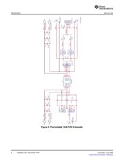
3 The Isolated CAN EVM Schematic ........................................................................................ 4
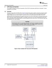
4 Basic Isolated CAN Transceiver EVM Operation ........................................................................ 6
5 Typical Waveforms Without Common-mode Loading .................................................................. 7
6 Common-mode Measurement Waveforms ............................................................................... 8
List of Tables
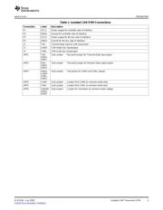
1 Isolated CAN EVM Connections ........................................................................................... 5
SLOU262 – July 2009 Isolated CAN Transceiver EVM 1
Submit Documentation Feedback
Verzeichnis
- ・ Blockdiagramm on Seite 4
- ・ Anwendungsbereich on Seite 10

