

herunterladen
User's Guide
SLLU207A–August 2014–Revised September 2015
ISO5852S Evaluation Module
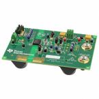
The manual describes the ISO5852S Evaluation Module (EVM). The ISO5852S EVM allows designers to
evaluate device AC and DC performance with a pre-populated 1-nF load or with a user-installed IGBT in
either of the standard TO-247 or TO-220 packages.
Warning: Note that although these devices provide galvanic isolation of up
to 5700 V, the EVM cannot be used for isolation voltage testing. Voltage
exceeding the EVM’s ratings (V
CC1
> 5.5 V, V
CC2
– V
EE2
> 30 V, or IGBT
Collector-Emitter Voltage V
CE
> 50 V) can damage the EVM resulting in
personal injury.
Contents
1 Overview...................................................................................................................... 3
2 EVM Setup and Precautions ............................................................................................... 3
2.1 Before You Begin................................................................................................... 3
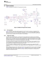
2.2 Power Supply Connections........................................................................................ 4
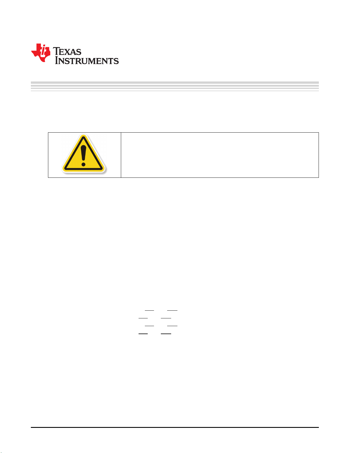
2.3 Signal Connections................................................................................................. 5
3 Example Measurements .................................................................................................... 6
4 Printed-Circuit Board....................................................................................................... 10
4.1 ISO5852S Operation.............................................................................................. 11
4.2 ISO5852S EVM Bill of Materials ................................................................................ 13
List of Figures
1 ISO5852S EVM Power Supply Schematic ............................................................................... 4
2 Output Power Supply for Unipolar (Left) or Bipolar (Right) Operation................................................ 4
3 ISO5852S EVM Signal Path Schematic.................................................................................. 5
4 ISO5852S EVM Input and Output With Unipolar Output Supply ...................................................... 6
5 ISO5852S EVM Input and Output With Bipolar Output Supply (V
CC2
= 15 V, V
EE2
= –8 V)......................... 7
6 ISO5852S EVM OUTH/L, DESAT, FLT, and RST With Unipolar Output Supply ................................... 7
7 ISO5852S EVM OUTH/L, RDY, FLT, and RST With Unipolar Output Supply....................................... 8
8 ISO5852S EVM OUTH/L, DESAT, FLT, and RST With Bipolar Output Supply..................................... 8
9 ISO5852S EVM OUTH/L, RDY, FLT, and RST With Bipolar Output Supply ........................................ 9
10 ISO5852S EVM ............................................................................................................ 10
List of Tables
1 Test Points .................................................................................................................. 12
2 Bill of Materials ............................................................................................................. 13
All trademarks are the property of their respective owners.
1
SLLU207A–August 2014–Revised September 2015 ISO5852S Evaluation Module
Submit Documentation Feedback
Copyright © 2014–2015, Texas Instruments Incorporated
Verzeichnis
- ・ Blockdiagramm on Seite 4 Seite 5
- ・ Anwendungsbereich on Seite 18 Seite 20