

herunterladen
User's Guide
SNVA057C–August 2002–Revised April 2013
AN–1247 LM2727 Evaluation Board
1 Introduction
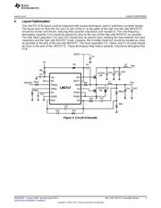
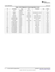
The LM2727 evaluation board has been designed for a wide variety of components in order to show the
flexibility of the LM2727 chips. The input voltage limitations are the same as the chip: 2.2 to 16 VDC. The
regulated output voltage range is from 0.6 V up to 85% of the input voltage. Output current is limited by
the components chosen, however, the size of this board and the limitation to SOIC-8 MOSFETs means a
realistic limit of about 10A.
The example design steps 12 V down to 3.3 V at 4A, with a switching frequency of 800 kHz. This design
can be modified by following the Design Considerations section of the LM2727/LM2737 N-Channel FET
Synchronous Buck Regulator Controller for Low Output Voltages Data Sheet (SNVS205).
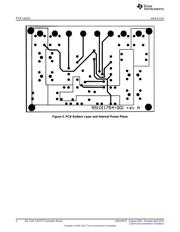
The board is four layers, consisting of signal/power traces on top and bottom, with one internal ground
plane and an internal split power plane. All planes are 1oz. copper, and the board is 62mil FR4 laminate.
2 Boot Voltage
The default circuit that comes with the LM2727 demo board uses a bootstrap diode and small capacitor
(D1 and Cboot) to provide enough gate-to-source voltage on the high side MOSFET to drive the FET. If a
separate rail is available that is more than twice the value of V
IN
, this higher voltage can be connected
directly to the BOOT pin, via the BOOT connector, with a 0.1µF bypass capacitor, Cc. In this case, D1 and
Cboot should be removed from the board. Do not connect both Cc and Cboot/D1 at the same time.
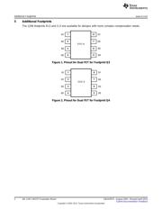
3 Dual MOSFET Footprints
The LM2727 demo board has two extra footprints for dual N-channel MOSFETs in SOIC-8 packages.
Footprint Q3 corresponds to devices with footprints such as the Si4816DY "LITTLEFOOT Plus" from
Vishay Siliconix. Footprint Q4 corresponds to devices with footprints such as the Si4826DY, also from
Vishay Siliconix.
4 Low-Side Diode
A footprint D2 is available for a Schottky diode to be placed in parallel with the low side FET. This can
improve efficiency because a discrete Schottky will have a lower forward voltage than the low side FET's
body diode. The footprint fits SMA size devices. If desired, the low side FET can be removed entirely, and
the LM2727 will run as an asynchronous Buck controller.
All trademarks are the property of their respective owners.
1
SNVA057C–August 2002–Revised April 2013 AN–1247 LM2727 Evaluation Board
Submit Documentation Feedback
Copyright © 2002–2013, Texas Instruments Incorporated
Verzeichnis