
herunterladen
User's Guide
SNVA124A–September 2005–Revised April 2013
AN-1397 LM2852X Demonstration Board
1 Introduction
This document describes the demonstration board for the LM2852X. The LM2852 is a 2A buck regulator
belonging to Texas Instruments Simple Synchronous™ family. The LM2852 input voltage can range from
2.85 V to 5.5 V. Output voltages are factory set from 0.8 V to 3.3 V in 100mV increments. On-chip type-
three compensation facilitates simple, low component count power supply design. Two frequency versions
of the LM2852 are available: 500 kHz (LM2852Y) and 1500 kHz (LM2852X). The demonstration board for
the LM2852X (1500 kHz version) is described in this document. A separate application note describes the
LM2852Y. For detailed information regarding component selection, consult the device-specific data sheet.
2 V
IN
, GND and V
OUT
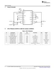
Three solder terminals are provided for connections to V
IN
, GND and V
OUT
. The input voltage to the
LM2852 is connected to two PVIN pins and an AVIN pin. PVIN is the supply connected to the output
power switches; AVIN powers the controller logic of the regulator. The demonstration board includes
filtering of the AVIN voltage using components R
F
and C
F
. The back side plane of the board is connected
to ground through the solder terminal via as well as vias underneath the exposed DAP of the LM2852.
3 Enable (EN)
The LM2852 enable pin is internally pulled up through a large resistance. The demonstration board
includes a via connected to the EN line to facilitate soldering a jumper wire if application of an enable
signal is desired.
4 C
IN
and C
INX
The demonstration board provides two capacitor footprints for the input capacitance. The larger footprint
holds the bulk of the capacitance, for example 47 µF. Additional high frequency filtering may also be
accomplished by adding a smaller capacitor – C
INX
. A 1 µF or 100 nF capacitor is commonly used for high
frequency filtering.
5 C
SS
The soft-start capacitor is used to control the startup behavior of the switching regulator. A 2.7 nF
capacitor yields approximately a 3 ms startup time.
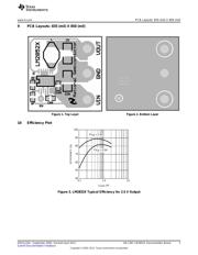
6 Output Filter - L, and C
O
Since the LM2852 uses on-chip compensation, the output filter component values must be restricted to a
certain range. The LM2852X is designed for ceramic output capacitors with ESR values below 10 mΩ.
The recommended inductance and capacitance for standard input and output voltages are 1 µH and 10
µF.
Simple Synchronous is a trademark of Texas Instruments.
All other trademarks are the property of their respective owners.
1
SNVA124A–September 2005–Revised April 2013 AN-1397 LM2852X Demonstration Board
Submit Documentation Feedback
Copyright © 2005–2013, Texas Instruments Incorporated
Verzeichnis
- ・ Blockdiagramm on Seite 2
- ・ Anwendungsbereich on Seite 4