


herunterladen
User's Guide
SNVA146C–January 2006–Revised April 2013
AN-1443 LM3100 Demonstration Board Reference Design
1 Introduction
The LM3100 synchronous rectifier buck regulator IC features all functions needed to implement a cost
effective, efficient, buck regulator capable of supplying 1.5A to the load. With minimum external
component count, very small overall board space is required for a typical application. The LM3100 works
well with ceramic output capacitors and contains dual, 40 V N-Channel synchronous switches. The part is
available in a thermally enhanced HTSSOP-20 package. The Constant ON-Time (COT) regulation scheme
requires no loop compensation, results in fast load transient response, and simplifies circuit
implementation. The controller does not rely on output capacitor ESR for stability, while maintaining the
simplicity of COT control. The operating frequency remains nearly constant with line and load variations
due to the inverse relationship between the input voltage and the ON-Time. Protection features include
V
CC
under-voltage lockout, thermal shutdown and gate drive under-voltage lockout.
This demonstration board provides a 3.3 V output with 1.5A load capability from a wide input voltage
range of 8 V to 36 V. The design is optimized for overall conversion efficiency and set to run at 250 kHz.
This application note contains the demo board schematic, PCB layout, Bill of Materials and circuit design
descriptions. Performance and typical operating waveforms are also provided for reference.
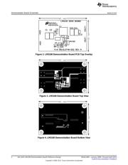
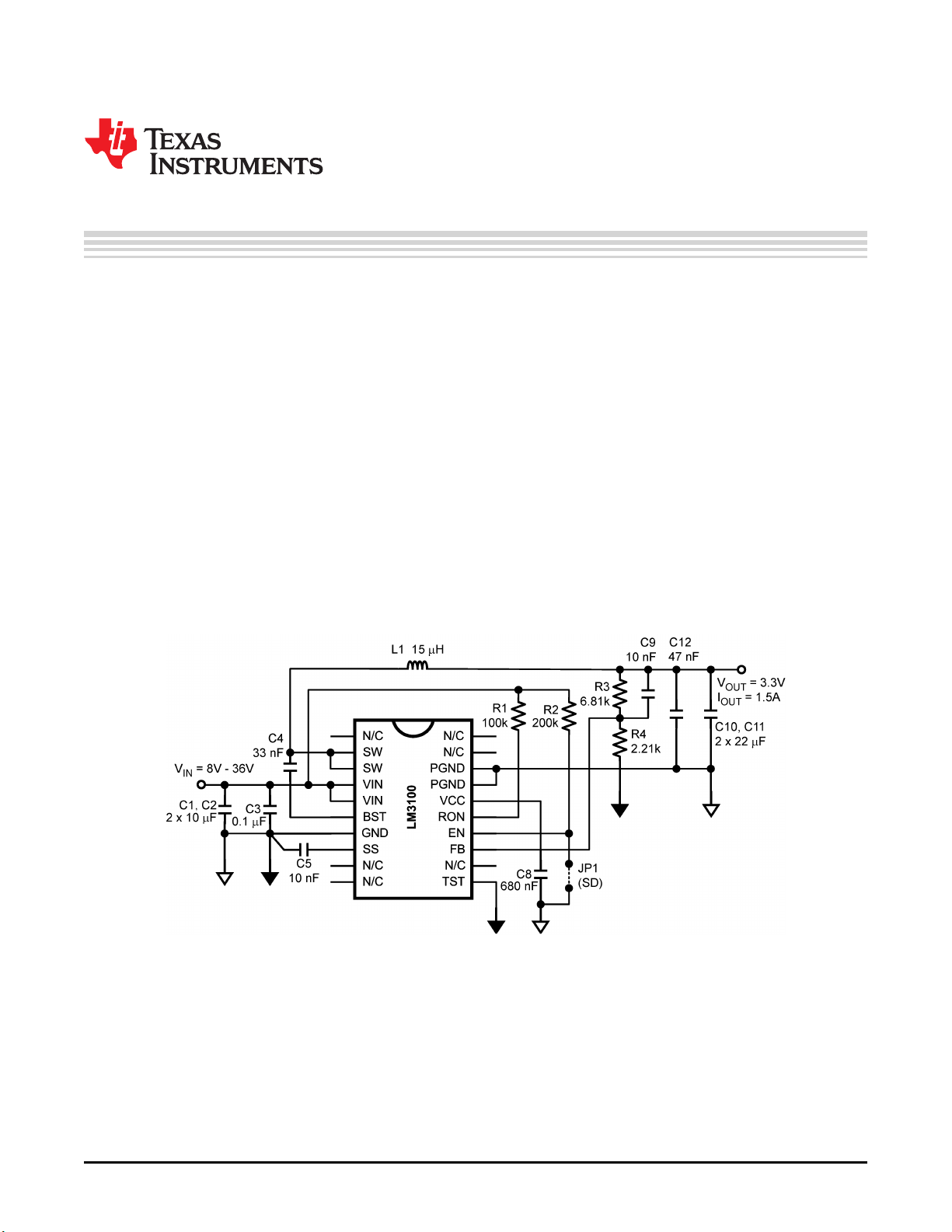
2 Demonstration Board Schematic
Figure 1. LM3100 Demonstration Board Schematic
All trademarks are the property of their respective owners.
1
SNVA146C–January 2006–Revised April 2013 AN-1443 LM3100 Demonstration Board Reference Design
Submit Documentation Feedback
Copyright © 2006–2013, Texas Instruments Incorporated
Verzeichnis
- ・ Blockdiagramm on Seite 1 Seite 2
- ・ Anwendungsbereich on Seite 10