

herunterladen
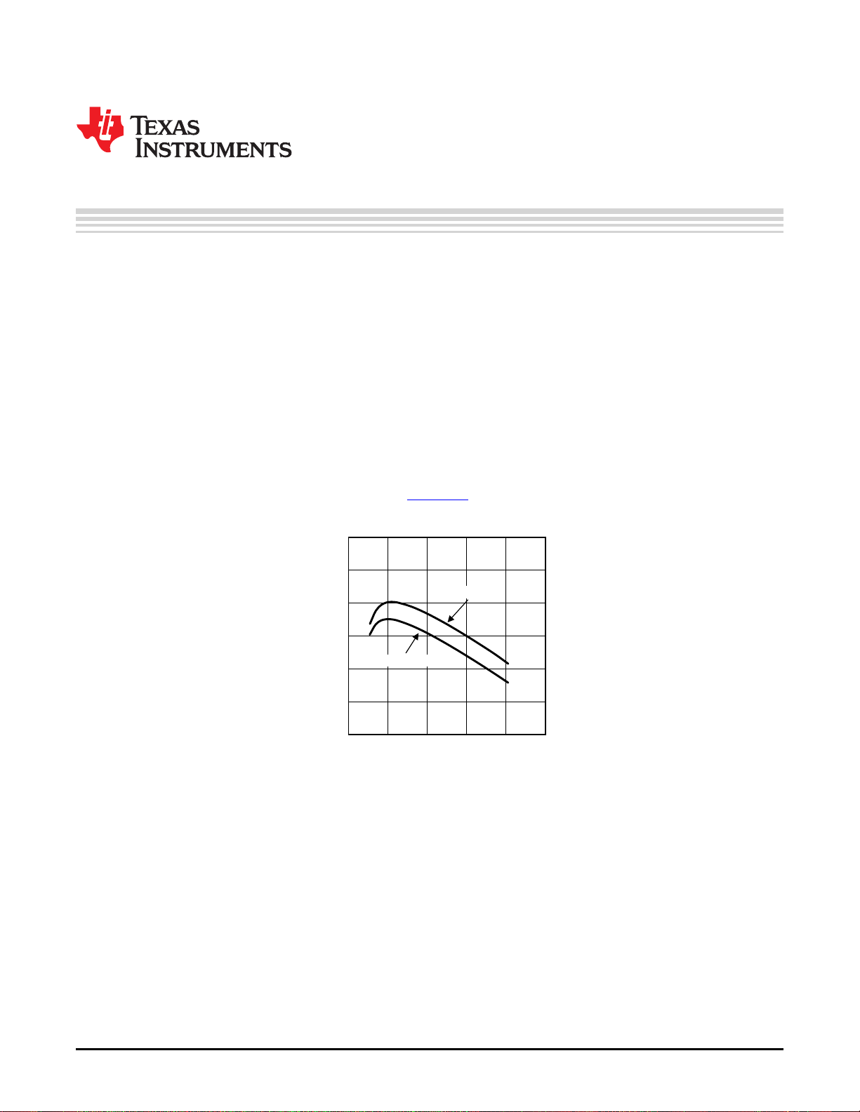
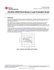
V
IN
(V)
EFFICIENCY (%)
100
95
90
85
80
75
70
0 16 32 48 64 80
Q1 is IPD200N15N3
Q1 is FDD3682
User's Guide
SNVA415C–June 2010–Revised May 2013
AN-2010 LM3423 Buck-Boost 2 Layer Evaluation Board
1 Introduction
This wide range evaluation board showcases the LM3423 NFET controller used with a buck-boost current
regulator. It is designed to drive 4 to 8 LEDs at a maximum average LED current of 700mA from a DC
input voltage of 10 to 70V.
The evaluation board showcases most features of the LM3423 including PWM dimming, fault and LED
status flags, output overvoltage protection and input under-voltage lockout. Note that there are two
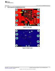
revisions of this PCB. The documentation for the latest revision (551600305-002 RevA) is shown first. The
schematic, layout and bill of materials for the first revision (551600305-001 Rev1) can be found at the end
of this document.
The buck-boost circuit can be easily redesigned for different specifications by changing only a few
components (see the Alternate Designs section found at the end of this application note). Note that design
modifications can change the system efficiency. See the LM3421/21Q1/21Q0 LM3423/23Q1/23Q0 N-Ch
Controllers for Constant Current LED Drivers (SNVS574) data sheet for a comprehensive explanation of
the device and application information.
Figure 1. Efficiency with 6 Series LEDS at 700mA
All trademarks are the property of their respective owners.
1
SNVA415C–June 2010–Revised May 2013 AN-2010 LM3423 Buck-Boost 2 Layer Evaluation Board
Submit Documentation Feedback
Copyright © 2010–2013, Texas Instruments Incorporated
Verzeichnis