

herunterladen
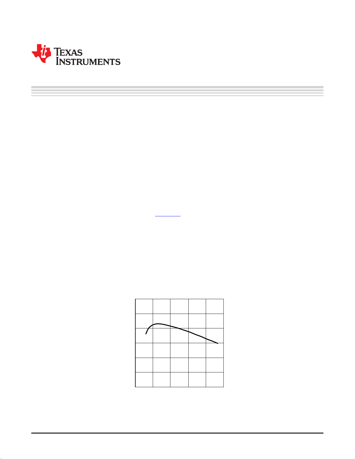
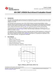
V
IN
(V)
EFFICIENCY (%)
100
95
90
85
80
75
70
0 16 32 48 64 80
User's Guide
SNVA397A–August 2009–Revised May 2013
AN-1967 LM3424 Buck-Boost Evaluation Board
1 Introduction
This wide range evaluation board showcases the LM3424 NFET controller used with a buck-boost current
regulator. It is designed to drive 4 to 10 LEDs at a maximum average LED current of 1A from a DC input
voltage of 10 to 70V.
The evaluation board showcases many of the LM3424 features including thermal foldback, analog
dimming, external switching frequency synchronization, and high frequency PWM dimming, among others.
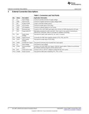
There are many external connection points to facilitate the full evaluation of the LM3424 device including
inputs, outputs and test points. Refer to Table 1 for a summary of the connectors and test points.
The buck-boost circuit can be easily redesigned for different specifications by changing only a few
components (see the Alternate Designs section). Note that design modifications can change the system
efficiency for better or worse.
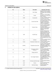
This application note is designed to be used in conjunction with the LM3424 datasheet as a reference for
the LM3424 buck-boost evaluation board. Refer to the LM3424 Constant Current N-Channel Controller
with Thermal Foldback for Driving LEDs (SNVS603) data sheet for a comprehensive explanation of the
device, design procedures, and application information.
2 Key Features
• Input: 10V to 70V
• Output: 4 to 10 LEDs at 1A
• Thermal Foldback / Analog Dimming
• PWM Dimming up to 10 kHz
• External Synchronization > 500 kHz
• Input Under-voltage and Output Over-voltage Protection
Figure 1. Efficiency with 9 Series LEDS AT 1A
All trademarks are the property of their respective owners.
1
SNVA397A–August 2009–Revised May 2013 AN-1967 LM3424 Buck-Boost Evaluation Board
Submit Documentation Feedback
Copyright © 2009–2013, Texas Instruments Incorporated
Verzeichnis