

herunterladen
VIN
FBCOMP
VCC
OUT
RT
UVLO GND
CS
SS
LM3430
L1
D1
Q1
C
C1
R
C1
C
F
C
SS
C
O2
C
INX
R
T
R
UV1
R
UV2
R
FB1
R
FB2
V
IN
V
O
VDHC
NC
R
SNS
C
SNS
R
S2
R
S1
+
C
IN2
C
IN1
SYNC
R
PD
OFF
Q2
+
C
O1
C
OX
1
2
10
8
11
4
3
5
7
9
6
12
C
C2
User's Guide
SNVA187C–January 2007–Revised May 2013
AN-1529 LM3430 Evaluation Board
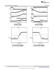
1 Specifications of the Board
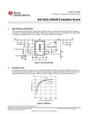
The Evaluation Board has been designed for testing of various circuits using the LM3430 boost regulator
controller. A complete schematic for all the components is shown in Figure 1. The board is two layers with
components and power paths in 1oz. copper. The board is 62mil FR4 laminate.
Figure 1. Circuit Schematic
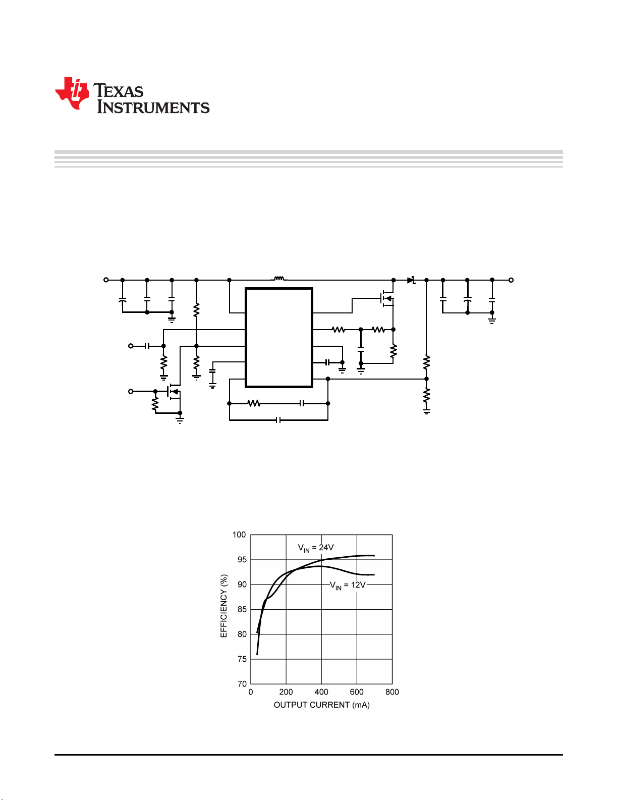
2 Example Circuit
The example circuit that comes on the evaluation board delivers a 48V ±2% output voltage at currents up
to 700 mA and switches at 600 kHz. The input voltage range is optimized between 10.8V and 26.4V. The
measured efficiency of the converter is 96% at an input voltage of 24V and an output current of 0.7A.
Figure 2. Efficiency
All trademarks are the property of their respective owners.
1
SNVA187C–January 2007–Revised May 2013 AN-1529 LM3430 Evaluation Board
Submit Documentation Feedback
Copyright © 2007–2013, Texas Instruments Incorporated
Verzeichnis
- ・ Blockdiagramm on Seite 1
- ・ Technische Daten on Seite 1
- ・ Anwendungsbereich on Seite 9
- ・ Elektrische Spezifikation on Seite 4 Seite 5 Seite 6